In this post we will go over an initial configuration for a Juniper switch. I will be using a Juniper EX4200. The initial configuration is very similar for other Juniper devices. I will include links throughout the post for relevant information.
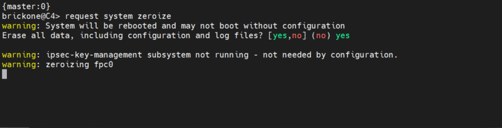
If you need to get back to factory default You can simply enter:
request system zeroize <– this will erase everything!
Below is how we will log in.
Factory default login prompt should show like below.
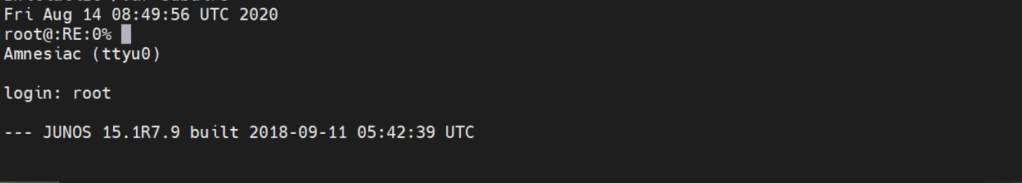
root@:RE:0% <– This is the freebsd shell. We leave this with the cli command
root@:RE:0% cli <– We leave this with cli
{master:0}
root> <– Operational mode prompt. Operational mode is used for monitoring and troubleshooting the device.
root> start shell
root@:RE:0%

/var/home <– Users home directories
/var/log <– Log files and tracing files
In operational mode we would use the file command to list files on the device.
File list <detail | recursive> <path> list ?

Operational mode is where we will do the most of our show commands. We can run operation commands from edit mode by placing the word run in front of the command.
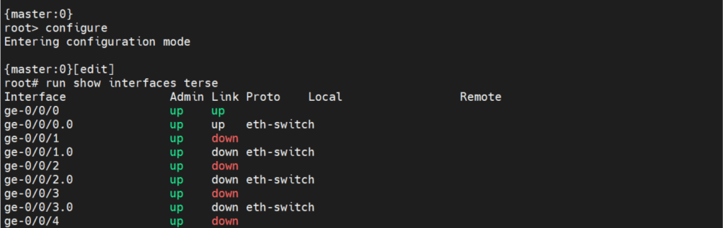
There are two commands to enter edit mode. Both configure and edit will get you to edit mode.

Edit mode is where we will do majority of configuration. There are some configuration commands, mainly request or set date commands. That are executed in operational mode.

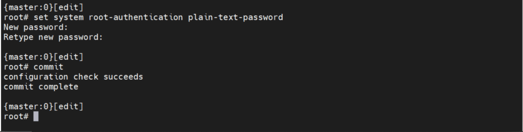
Before we can make any configuration changes, we need to set the system root-authentication.

The command is issued either at the top of the hierarchy [edit] or
[edit system root-authentication] hierarchy.
{master:0}[edit system root-authentication]
root# set plain-text-password <– Upon enter will prompt for password
New password: <– The characters are not displayed
Retype new password:
One of the best features about JunOS is the commit command.

The few you will probably use the most are
Commit check <– Checks candidate configuration, does not apply it to active configuration
Commit confirmed # <– #= number in minutes between 1-65535. Default is 10m if no time is specified. Will apply candidate configuration to active configuration for time specified. Can be permanently configured by entering commit
Commit and-quit <– Commits candidate configuration to active and exits to operational mode.
The interesting thing about Juniper devices is the ability to rollback the configuration. By default Juniper keeps the last 50 (0-49) configurations. 0 being the active configuration. The configurations are sequentially moved after each commit.

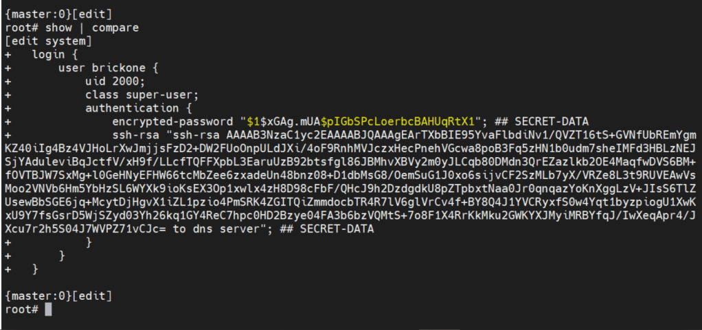
Now let’s create the user we will be using to login to our device.
set system login user brickone uid 2000 <– creates user and assigns specific user id
set system login user brickone class super-user <– You can assign a system defined user class, or create your own.

set system login user brickone authentication encrypted-password “$1$xGAg.mUA$pIGbSPcLoerbcBAHUqRtX1” <– You can paste in an encrypted password or use
set system login user brickone authentication plain-text-password
We can also set a private key if you have one
set system login user brickone authentication ssh-rsa “key here”
Whenever you are making changes or before a commit. You can use show | compare <– Shows differences of candidate configuration against active configuration.
- Active configuration is the current configuration being utilized by the device
- Candidate configuration is a copy of the active configuration in the device’s memory, created upon entering edit mode. No changes are implemented until a commit command is executed.
We can easily configure ssh access with a single command.
Set system services ssh <– Allow ssh access to device
System services are configured under the system services hierarchy.
When in edit mode, we can view just the configuration of our position in the hierarchy. With a simple show command.

To view the full configuration we can enter top , then show

When navigating the Juniper cli, Top will take us back to the top of the configuration hierarchy.
To change the device host-name we will enter
Set system hostname name
It’s important to set the device time and logging. Both are necessary for efficient troubleshooting. Depending on your setup, it could just be a single command.
set system ntp server 0.0.0.0 <– enter ntp server ip address
set date YYYYMMDDHHmm.ss <– Manually set system date & time
set system time-zone America/Detroit <– Change system time-zone
If your ntp server uses authentication (good idea) then the following commands may be closer to what you are looking for.
set system ntp boot-server 192.168.0.20 <–NTP server used upon boot
set system ntp authentication-key 1 type md5 <– NTP key & key algorithm
set system ntp authentication-key 1 value “$9$/x1ptpORESM8xGD” <– Juniper automatically encrypts passwords in configuration
set system ntp server 192.168.0.20 prefer <– Preferred NTP server
set system ntp trusted-key 1 <– Which key to use with server
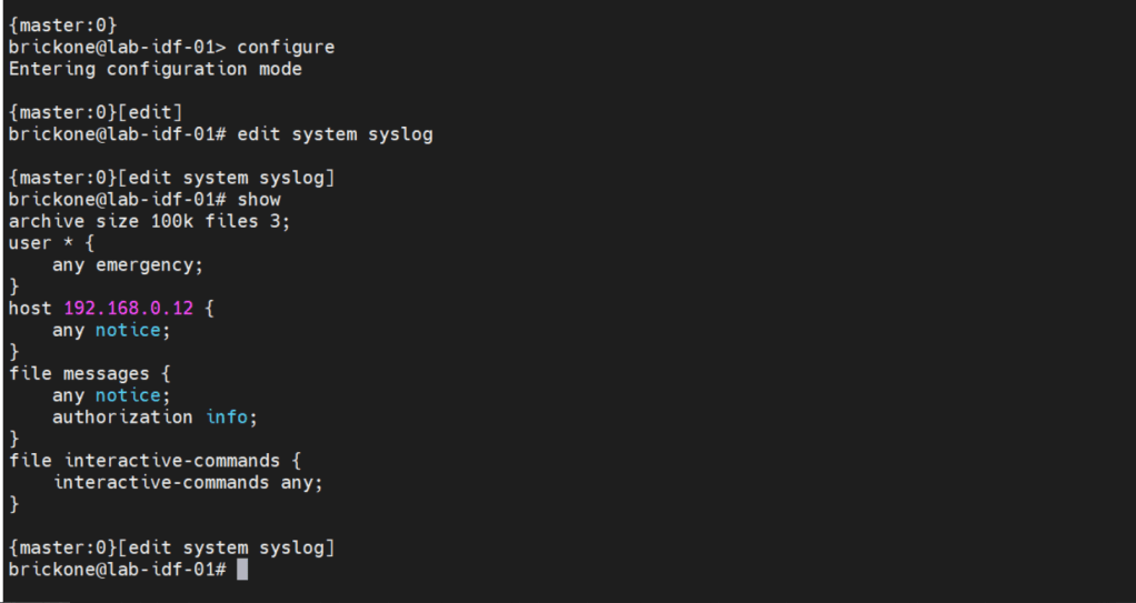
With accurate system clock, comes accurate logging, which enables more efficient troubleshooting.
By default, log messages are sent to the messages log file.

To send log messages to a server we can navigate to the system syslog hierarchy. We can then set the server address, port, protocol, user to be notified of any or specific log events. We can alter a nice amount of log settings here, as well as change the file the device logs to.
That configuration will do us no good if we do not have any interfaces configured to pass traffic. A cool feature about juniper devices is that they come with a dedicated management interface. The management interface does not allow transit traffic. It is purely for managing the device. Configuring that interface is the same as our transit interfaces. Juniper devices require the configuration of a logical unit on the physical interface.
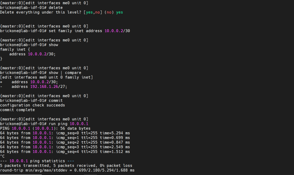

The family is the protocol that will be used to communicate on the logical interface. The interface must have a unit 0. The unit number is arbitrary, but mandatory.
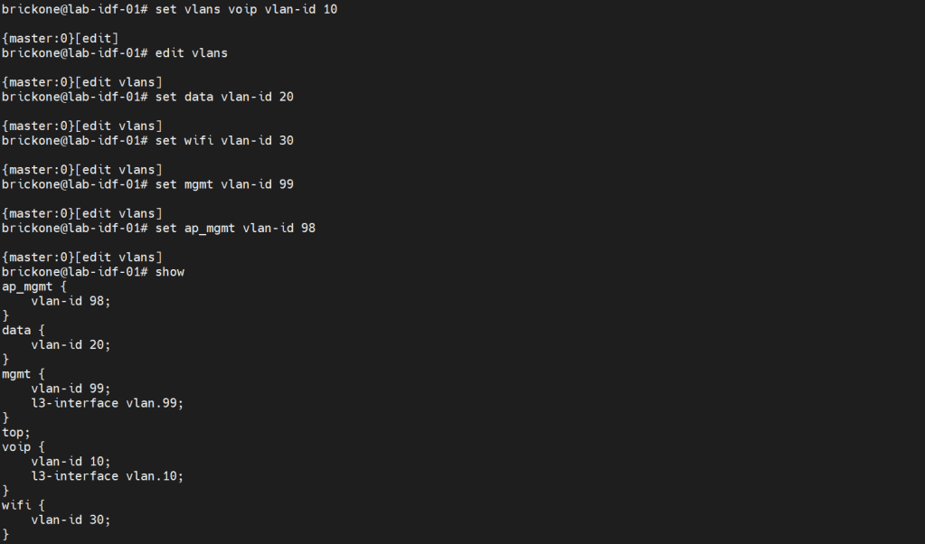
Configuring vlans is pretty straightforward. The vlan has to be specified by name, then assigned a tag value.
Set vlans name vlan-id #
root# set vlans MGMT vlan-id 99
To utilize our vlans, we need to configure our interfaces. We need access ports, which normally go to end devices. We also need to configure trunk ports which normally go to other networking devices. Good practice is to make interface ranges.
It is a very organized approach, but it’s important to remember that in the configuration. When there is a conflict, the range configured above the conflicting range will win.
Set interfaces interface-range name ? <– you configure this just like an interface.

Set interfaces interface-range name unit 0 family ethernet-switching
Set interfaces interface-range name unit 0 family inet
Set interfaces interface-range name description “description”
Set interfaces interface-range name member|member-range ge-0/0/# to ge-0/0/#

# You can set the vlan members either with name or number, the result is the same. You enable or disable poe on an interface with the set poe interface command. You can verify poe functionality with show poe controller operational mode command.
For trunk interfaces there are a few differences from other vendors that are worth noting. When a trunk interface is configured, you need to explicitly set the allowed vlans, and native vlan. The next part is that for our vlan interfaces. We need to create the vlan interface, then associate a vlan to it.
My ge-0/0/28 interface is connected to an upstream switch. It is good practice to limit the vlans allowed on a trunk port. Depending on your setup. The switch may do the routing for the vlan, or a router. All vlans don’t need a layer 3 interface configured. Remember that when configuring a Juniper device. As long as all the pieces are there during commit, the configuration will pass.
Set interfaces <interface> unit 0 family inet address <address/prefix>
Set vlans <vlan-name> vlan-id <#>
Set vlans <vlan-name> l3-interface <interface>
set interfaces vlan.99 family inet address 192.168.0.253/24
set vlans mgmt l3-interface vlan.99
set interfaces vlan.10 family inet address 10.0.10.2/24
set vlans voip l3-interface vlan.10
If we needed a DHCP server on our network. We could use our switch to facilitate this. I will configure it for one of our vlans.
#Configure DHCP service
Set system services dhcp-local-server <group-name> interface <interface>
Set system services dhcp-local-server group <group-name> interface <interface>
Set access address-assignment pool <pool-name> family <family> network <address/prefix>
#Range for DHCP pool
Set access address-assignment pool <pool-name> family <family> range <range-name> low <low-ip-address>
Set access address-assignment pool <pool-name> family <family> range <range-name> high <high-ip-address>
# Configure DHCP pool attributes
Set access address-assignment pool <pool-name> family <family> dhcp-attributes router <gateway-ip-address>
Set access address-assignment pool <pool-name> family <family> dhcp-attributes maximum-lease-time <seconds>
Set access address-assignment pool <pool-name> family <family> dhcp-attributes option <option-id-number> option-type <option-value>

# If you just paste a lot of set commands, it will overload the buffer. All the commands will not be accepted by the command prompt. Using the load set terminal will allow you to paste a large amount of set commands.
Configuring layer 2 security for our device will help mitigate some issues we may encounter down the line. There is always more we can do for security. We will keep it simple; we want to enable DHCP snooping for the vlans that will utilize DHCP. DHCP snooping builds a table, that maps the clients ip and mac address delivered by the DHCP server. It helps mitigate rogue DHCP servers, by designating a trusted port to allow DHCP server Offer messages.
We will add in DAI (Dynamic Arp Inspection); it uses that table as a list of authorized addresses that can perform arp requests. It protects against gratuitous arps, attempts to alter the flow of traffic for a host.
You can manually add mac addresses to the trusted list. You may also add manual DHCP snooping bindings to the tablet. It’s not very efficient, but it can help with troubleshooting.
IP source guard uses the DHCP snooping binding table. It uses this table to check if a host’s packets will be permitted or denied. If the packet on an untrusted port is not matched in the DHCP snooping table. It is discarded. By default, on Juniper trunk interfaces are trusted for DHCP snooping, IP source guard, and DAI.
Mac limiting on an interface, is a way to protect from mac flooding attacks. They are used to overload the cam table. Once no more mac address can be learned. All traffic is flooded, essentially turning our switch into a hub.
All four are configured under the Ethernet-switching-options secure-access-port hierarchy
#Configure DHCP snooping
set vlan <vlan-name> examine-dhcp
set vlan <all> examine-dhcp
#Configure DHCP Snooping Manual Binding
set ethernet-switching-options secure-access-port interface <interface> static-ip <ip-address> vlan <vlan-name> mac <mac-address>
[edit ethernet-switching-options secure-access-port]
set interface <interface> static-ip <ip-addr> vlan <#> mac <mac-addr>
#Configure DAI
set vlan <vlan-name> arp-inspection
set vlan<all> arp-inspection
#Configure Static Arp table entry
[edit interfaces <interface> unit <#> family <family> address <address>]
set arp ip-address mac <mac-address>
#Configure IP source guard
set vlan <vlan-name> ip-source-guard
set vlan<all> ip-source-guard
#Configure Mac limiting
set interface <interface> mac-limit # action <action>
set interface <all> mac-limit # action <action>
[edit vlans]
set <vlan> mac-limit # action <action>
#Configure Static Mac
set interface <interface> allowed-mac <mac-address>
#If you need to isolate device communication in a vlan
[edit vlans]
set <vlan> no-local-switching

The action drop will just drop packets of the exceeding mac address on the port. You could also have the port disable, then re-enable after a certain amount of time, just like with BPDU errors.
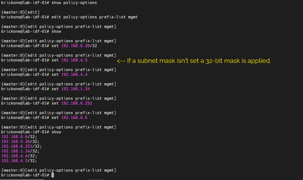
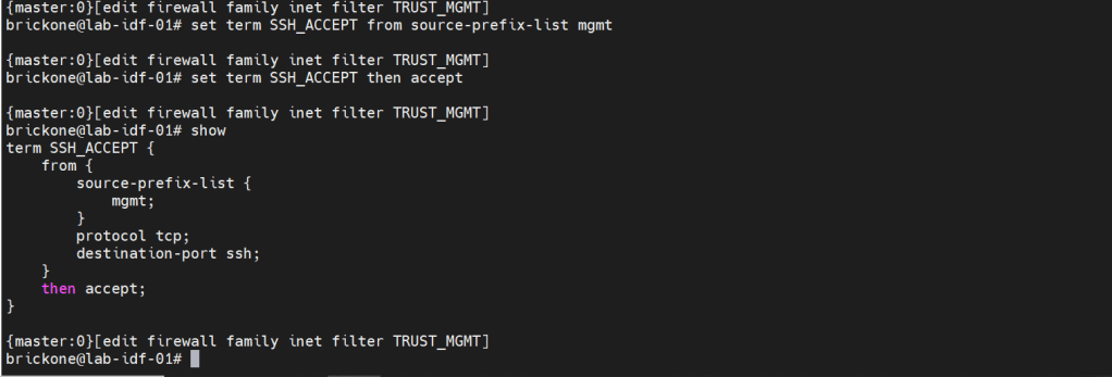
We will secure our device further by only allowing specific subnets or hosts to remotely access our device. On Juniper devices we will use a firewall filter to discriminate control plane traffic destined for the routing engine. We want to make sure we do not lock ourselves out of the device. As well as drop other traffic. At the end of all firewall filters, there is an implicit deny any. Juniper firewall filters use terms with from for matching, then for action statements. The steps are simple, we will configure our prefix list, apply it in a firewall filter configuration, along with our other match conditions. We will add an accept all at the end of the firewall filter. Then apply the firewall filter to our loopback interface.
#Create prefix-list
set policy-options prefix-list <name> <ip-address/prefix>
#Create firewall filter
set firewall family <family> filter <name> term <term-name> from <match condition>
set firewall family <family> filter <name> term <term-name> then <action>
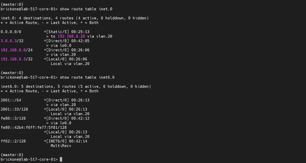
Before we configure our firewall filter, we need to configure connectivity. The only devices our switch can reach are directly connected devices. Since those will be the only routes in the routing table without administrative intervention. Because this device only has one path off the network. We will just configure a default route to our next-hop device.
#Static route configuration
set routing-options static route 0.0.0.0/0 next-hop <ip-address>
set routing-options static route 0/0 next-hop 192.168.0.20

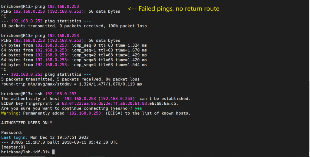


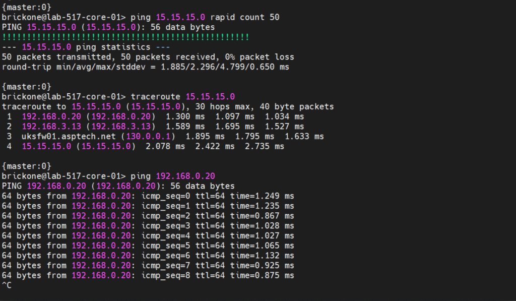
To verify that our switch is operating as we expected. We need to run show commands to verify reach-ability.
#To view if a port is moving traffic

#To view mac addresses on a port or vlan
show ethertnet-switching

#To view DHCP snooping bindings and dhcp server bindings
#To view routing table & test reach-ability
That’s all for now. Be wary when buying used gear, for labs it’s fine. My 48 port and 24 port ex4200’s dhcp snooping did not function at all. As always thank you for your time, and have a great day.
