Hello my name is Kaylan. I'm constantly working towards a better self. I enjoy working on and with technology. Learning is the fabric of a fulfilling life in my opinion.
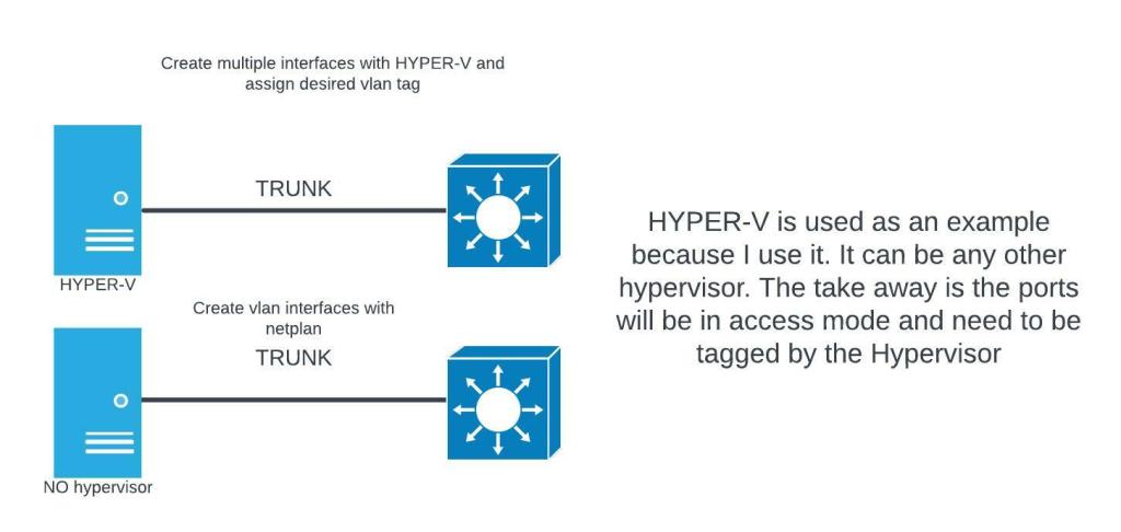
This is going to be a quick post about getting started with KVM. If you have used a type-1 hypervisor before, then you will be familiar with the topology used here. The adding of openvswitch is to allow trunk ports on our virtual switches. By default, most hypervisors only have access ports. To complete this setup you need a physical networking device that can do trunking (switch). Either a linux machine with a graphical desktop or windows machine with WSL installed. Two available ethernet ports on your computer. One connection for management. The other connection will be the vm trunk. I will be using Ubuntu 20.04. The hypervisor can be hosted on your server or ubuntu desktop. In this tutorial I’m using Ubuntu desktop 20.04.
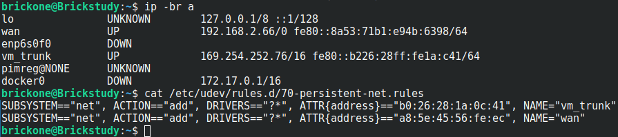
#Before we create the bridge, you should have an interface picked out. #
#Giving the interfaces a distinguishing name can assist with troubleshooting.
#You can create a text file in the /etc/udev/rules.d/ directory named #70-persistent-net.rules. The changes will not apply until you reboot the system.
#You only have to add the tagging to the bridge and interface once.
#The vms’s interface tag configuration will have to be applied again if there is a restart.
#We will make a #simple script to find our desired vm interface and give it the tags we want.
sudo ovs-vsctl set port br1 tag=99 ← Sets the vlan tag of the interface
sudo ovs-vsctl set port br1 trunks=[2-250]
# ^Sets the vlans on the trunk, can be a range as well as separated by commas
sudo ovs-vsctl set port br1 vlan_mode=native-untagged ← Sets the interface to use native vlan
#The bridge is down when created. We should bring the bridge up and #assign an address to it.
#The configured address should be in the subnet of the tag on the bridge.
#For me vlan 99 = 192.168.0.0/24
#The below commands will not persist after a reboot.
sudo ip addr add 192.168.0.6/24 dev br1
sudo ip link set br1 up
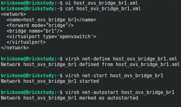
#The above commands import the bridge into KVM, start the bridge, then
#enable the bridge to start on system boot.
#You can now create a vm via the command line or the gui.
#We can open up virt-manager and start installing our first vm
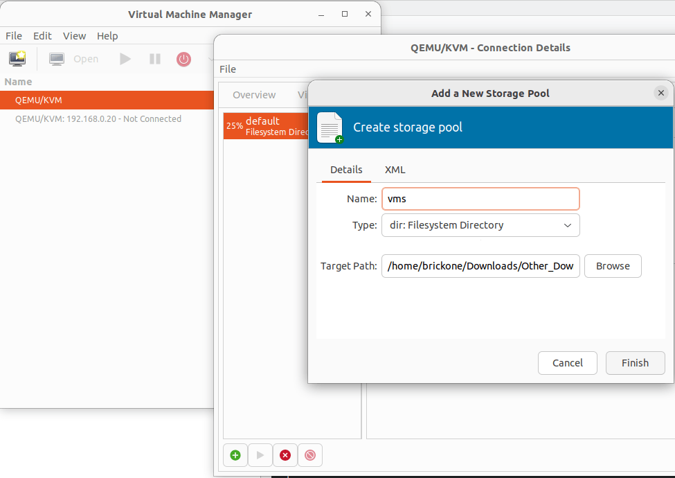
#Start by creating the storage pools. These are the locations of your vms and installation images.
#Double click the Qemu/KVM
click the green plus sign to create the storage pools
Verify in the Virtual Networks tab that our bridge is listed
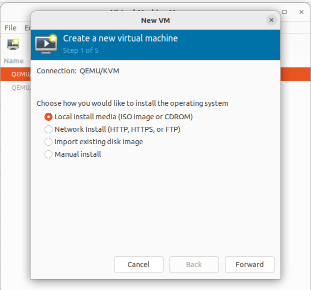
Click File> New Virtual Machine
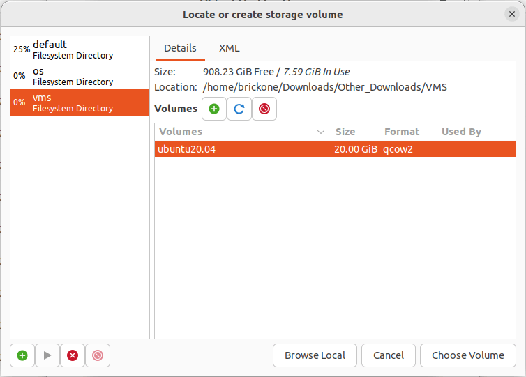
To install from an ISO file pick Local Install > Browse to the iso file on the configured storage pool. If you previously added the image to the folder. Click refresh, highlight your selection and click choose volume.
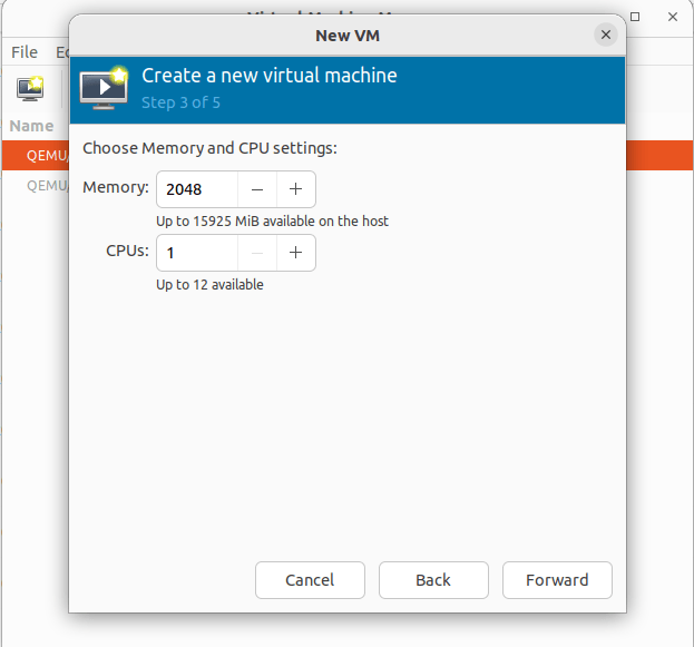
Set the desired memory and cpu settings for this vm
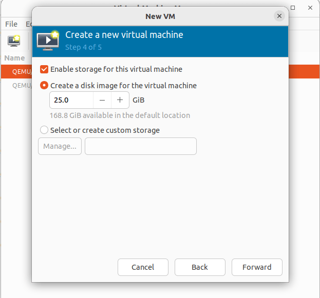
Create an hard drive image for the machine. You can change where the drive is located by clicking the Select or create customer storage option.
All storage options can be altered later. Just like the default for creating a vm.
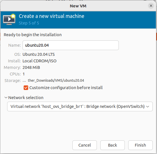
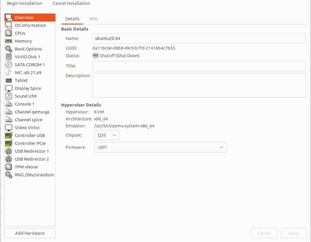
Changing the vm name can be done during or after creation. Click customer configuration before install to alter the vm before launching for install. This is needed if UEFI isn’t set as a default. The network selection should be set to our created openvswitch bridge.
Click finish, then select overview. If your OS requires UEFI to boot. Under the Hypervisor Details section, click the firmware tab and select UEFI. If everything is correct click begin installation.
Select you language of preference
If you have trouble viewing, click view>resize vm
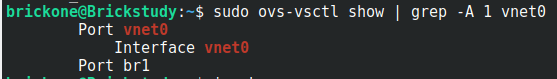
At the above screen, we need to go back over to our command line.
Making a script will be much easier as the amount of vms grows.
We need to set the tagging so the vm can communicate.
Lets grab the last six of the mac address and add it to our script
You can get it from the installation screen as well
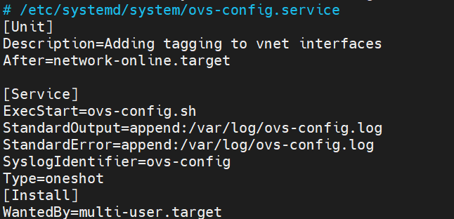
#You can place the script in one of the default system paths for programs.
sudo touch /usr/local/sbin/ovs-config.sh
sudo vi /usr/local/sbin/ovs-config.sh
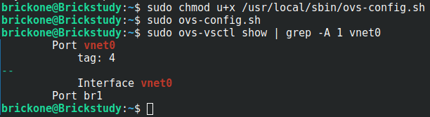
We need to make the script executable.
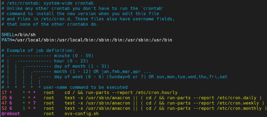
Then add it to a cron job. Whichever works best for you. When the VMs are restarted, the vnet interface is destroyed and is recreated when the VM comes back online.
We will make the script run on boot.
If this works correctly, our vm will be natively in vlan 4. It will also be able to communicate with vlan interfaces in any of the configured vlans on the trunk port.
Now our vm has network access
You will need to add tags to a vm’s interface whenever they are powered off and back on again.
I really enjoyed migrating from Hyper-V to kvm. I learned so much. Thank you for your time and have a great day!
If you need assistance finishing the installation. Here is the link to a Ubuntu installation tutorial.
In this post we will go over an initial configuration for a Juniper switch. I will be using a Juniper EX4200. The initial configuration is very similar for other Juniper devices. I will include links throughout the post for relevant information.
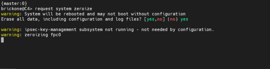
If you need to get back to factory default You can simply enter:
request system zeroize <– this will erase everything!
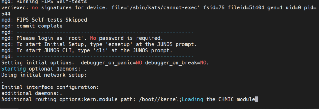
Below is how we will log in.
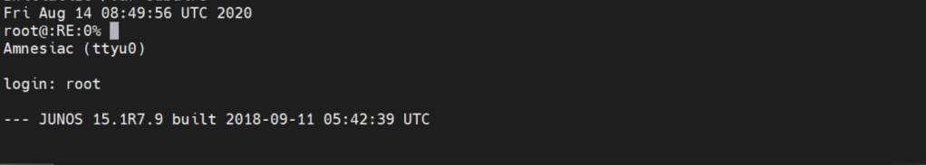
Factory default login prompt should show like below.
root@:RE:0% <– This is the freebsd shell. We leave this with the cli command
root@:RE:0% cli <– We leave this with cli
{master:0}
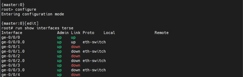
root> <– Operational mode prompt. Operational mode is used for monitoring and troubleshooting the device.
Operational mode is where we will do the most of our show commands. We can run operation commands from edit mode by placing the word run in front of the command.
There are two commands to enter edit mode. Both configure and edit will get you to edit mode.
Edit mode is where we will do majority of configuration. There are some configuration commands, mainly request or set date commands. That are executed in operational mode.
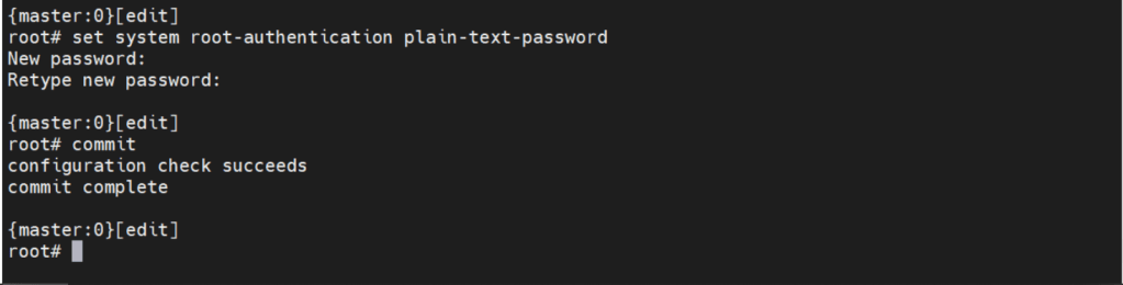
Before we can make any configuration changes, we need to set the system root-authentication.
The command is issued either at the top of the hierarchy [edit] or
[edit system root-authentication] hierarchy.
{master:0}[edit system root-authentication]
root# set plain-text-password <– Upon enter will prompt for password
Commit check <– Checks candidate configuration, does not apply it to active configuration
Commit confirmed # <– #= number in minutes between 1-65535. Default is 10m if no time is specified. Will apply candidate configuration to active configuration for time specified. Can be permanently configured by entering commit
Commit and-quit <– Commits candidate configuration to active and exits to operational mode.
The interesting thing about Juniper devices is the ability to rollback the configuration. By default Juniper keeps the last 50 (0-49) configurations. 0 being the active configuration. The configurations are sequentially moved after each commit.
Now let’s create the user we will be using to login to our device.
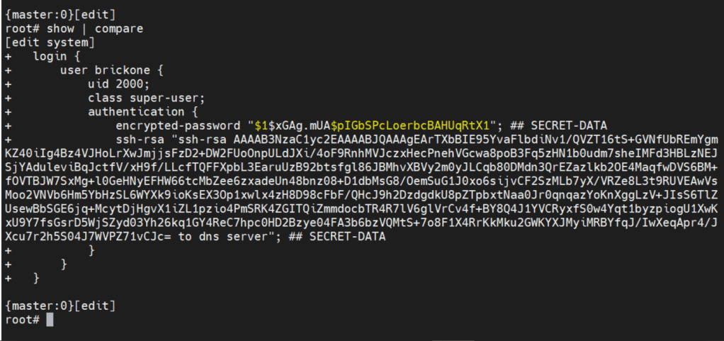
set system login user brickone uid 2000 <– creates user and assigns specific user id
set system login user brickone class super-user <– You can assign a system defined user class, or create your own.
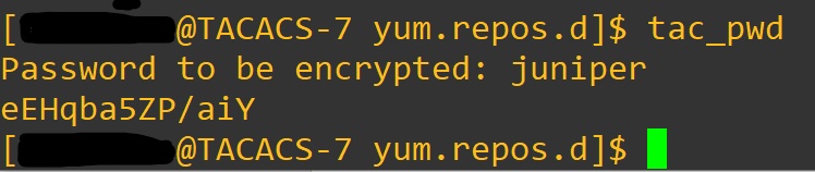
set system login user brickone authentication encrypted-password“$1$xGAg.mUA$pIGbSPcLoerbcBAHUqRtX1” <– You can paste in an encrypted password or use
set system login user brickone authentication plain-text-password
We can also set a private key if you have one
set system login user brickone authentication ssh-rsa “key here”
Whenever you are making changes or before a commit. You can use show | compare <– Shows differences of candidate configuration against active configuration.
Active configuration is the current configuration being utilized by the device
Candidate configuration is a copy of the active configuration in the device’s memory, created upon entering edit mode. No changes are implemented until a commit command is executed.
It’s important to set the device time and logging. Both are necessary for efficient troubleshooting. Depending on your setup, it could just be a single command.
set system ntp server 0.0.0.0 <– enter ntp server ip address
set date YYYYMMDDHHmm.ss <– Manually set system date & time
set system time-zoneAmerica/Detroit <– Change system time-zone
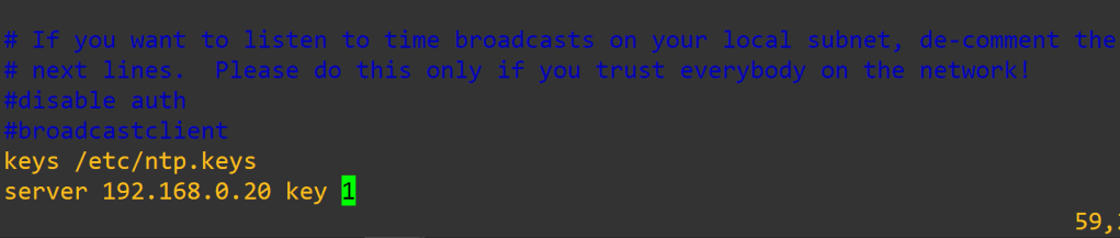
If your ntp server uses authentication (good idea) then the following commands may be closer to what you are looking for.
set system ntp boot-server 192.168.0.20 <–NTP server used upon boot
set system ntp authentication-key 1 type md5 <– NTP key & key algorithm
set system ntp authentication-key 1 value “$9$/x1ptpORESM8xGD” <– Juniper automatically encrypts passwords in configuration
set system ntp server 192.168.0.20 prefer <– Preferred NTP server
set system ntp trusted-key 1 <– Which key to use with server
With accurate system clock, comes accurate logging, which enables more efficient troubleshooting.
By default, log messages are sent to the messages log file.
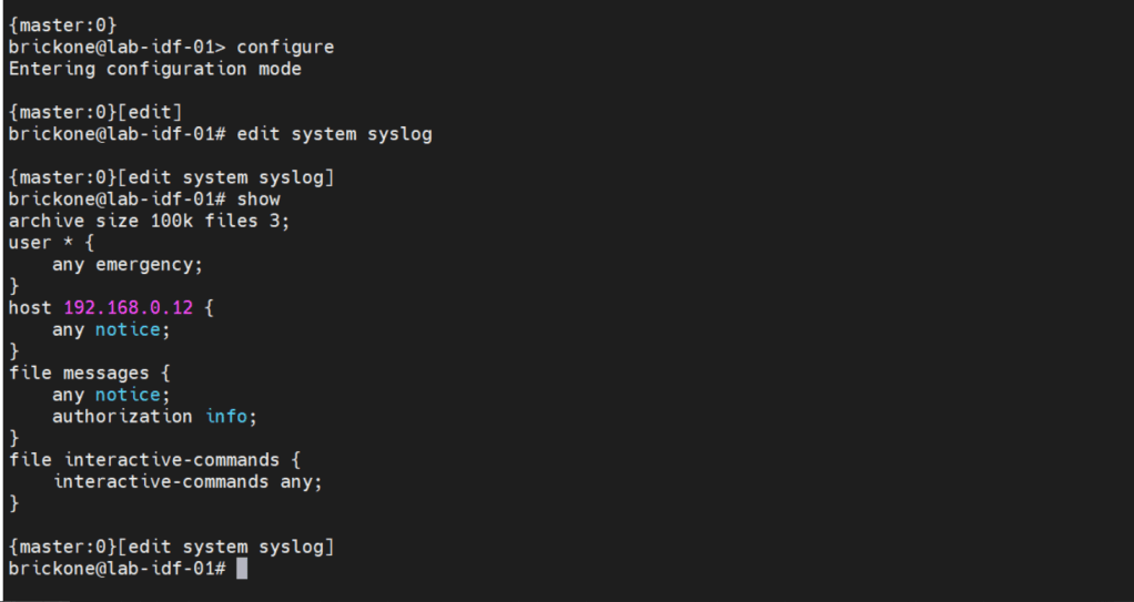
To send log messages to a server we can navigate to the system syslog hierarchy. We can then set the server address, port, protocol, user to be notified of any or specific log events. We can alter a nice amount of log settings here, as well as change the file the device logs to.
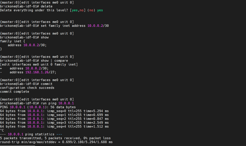
That configuration will do us no good if we do not have any interfaces configured to pass traffic. A cool feature about juniper devices is that they come with a dedicated management interface. The management interface does not allow transit traffic. It is purely for managing the device. Configuring that interface is the same as our transit interfaces. Juniper devices require the configuration of a logical unit on the physical interface.
The family is the protocol that will be used to communicate on the logical interface. The interface must have a unit 0. The unit number is arbitrary, but mandatory.
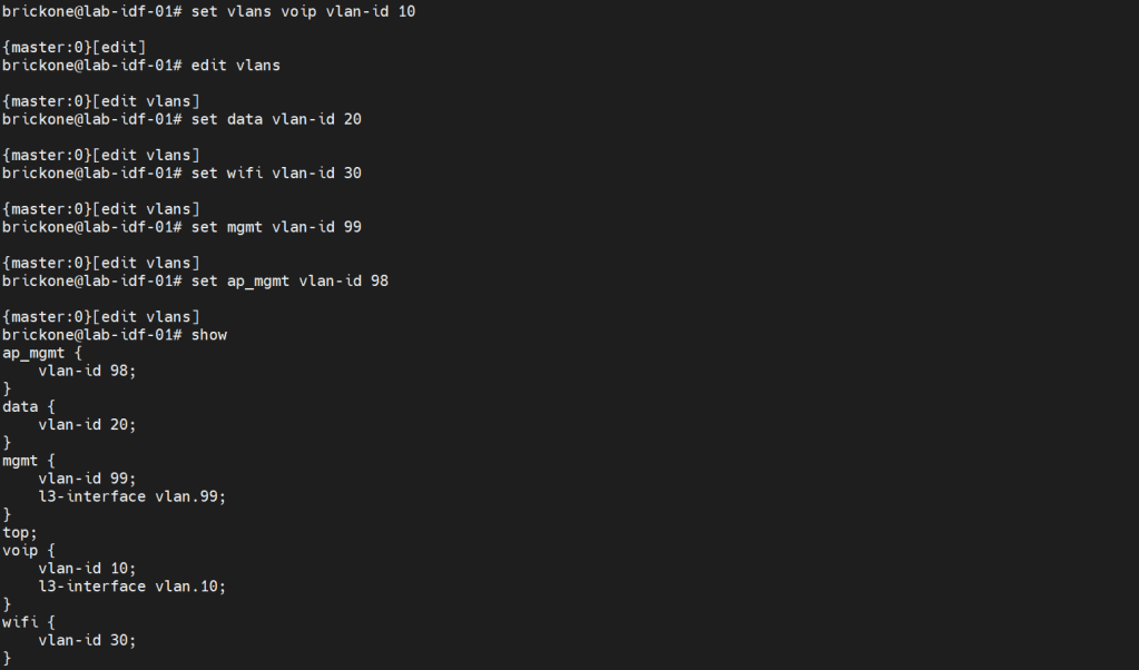
Configuring vlans is pretty straightforward. The vlan has to be specified by name, then assigned a tag value.
Set vlans name vlan-id #
root# set vlans MGMT vlan-id 99
To utilize our vlans, we need to configure our interfaces. We need access ports, which normally go to end devices. We also need to configure trunk ports which normally go to other networking devices. Good practice is to make interface ranges.
It is a very organized approach, but it’s important to remember that in the configuration. When there is a conflict, the range configured above the conflicting range will win.
Set interfaces interface-range name ? <– you configure this just like an interface.
Set interfaces interface-range name unit 0 family ethernet-switching
Set interfaces interface-range name unit 0 family inet
Set interfaces interface-range name description “description”
Set interfaces interface-range name member|member-range ge-0/0/# to ge-0/0/#
# You can set the vlan members either with name or number, the result is the same. You enable or disable poe on an interface with the set poe interface command. You can verify poe functionality with show poe controller operational mode command.
For trunk interfaces there are a few differences from other vendors that are worth noting. When a trunk interface is configured, you need to explicitly set the allowed vlans, and native vlan. The next part is that for our vlan interfaces. We need to create the vlan interface, then associate a vlan to it.
My ge-0/0/28 interface is connected to an upstream switch. It is good practice to limit the vlans allowed on a trunk port. Depending on your setup. The switch may do the routing for the vlan, or a router. All vlans don’t need a layer 3 interface configured. Remember that when configuring a Juniper device. As long as all the pieces are there during commit, the configuration will pass.
Set interfaces <interface> unit 0 family inet address <address/prefix>
Set vlans <vlan-name> vlan-id <#>
Set vlans <vlan-name> l3-interface <interface>
set interfaces vlan.99 family inet address 192.168.0.253/24
set vlans mgmt l3-interface vlan.99
set interfaces vlan.10 family inet address 10.0.10.2/24
set vlans voip l3-interface vlan.10
If we needed a DHCP server on our network. We could use our switch to facilitate this. I will configure it for one of our vlans.
#Configure DHCP service
Set system services dhcp-local-server <group-name> interface <interface>
Set system services dhcp-local-server group <group-name> interface <interface>
Set access address-assignment pool <pool-name> family <family> network <address/prefix>
#Range for DHCP pool
Set access address-assignment pool <pool-name> family <family> range <range-name> low <low-ip-address>
Set access address-assignment pool <pool-name> family <family> range <range-name> high <high-ip-address>
# Configure DHCP pool attributes
Set access address-assignment pool <pool-name> family <family> dhcp-attributes router <gateway-ip-address>
Set access address-assignment pool <pool-name> family <family> dhcp-attributes maximum-lease-time <seconds>
Set access address-assignment pool <pool-name> family <family> dhcp-attributes option <option-id-number> option-type <option-value>
# If you just paste a lot of set commands, it will overload the buffer. All the commands will not be accepted by the command prompt. Using the load set terminal will allow you to paste a large amount of set commands.
Configuring layer 2 security for our device will help mitigate some issues we may encounter down the line. There is always more we can do for security. We will keep it simple; we want to enable DHCP snooping for the vlans that will utilize DHCP. DHCP snooping builds a table, that maps the clients ip and mac address delivered by the DHCP server. It helps mitigate rogue DHCP servers, by designating a trusted port to allow DHCP server Offer messages.
We will add in DAI (Dynamic Arp Inspection); it uses that table as a list of authorized addresses that can perform arp requests. It protects against gratuitous arps, attempts to alter the flow of traffic for a host.
You can manually add mac addresses to the trusted list. You may also add manual DHCP snooping bindings to the tablet. It’s not very efficient, but it can help with troubleshooting.
IP source guard uses the DHCP snooping binding table. It uses this table to check if a host’s packets will be permitted or denied. If the packet on an untrusted port is not matched in the DHCP snooping table. It is discarded. By default, on Juniper trunk interfaces are trusted for DHCP snooping, IP source guard, and DAI.
Mac limiting on an interface, is a way to protect from mac flooding attacks. They are used to overload the cam table. Once no more mac address can be learned. All traffic is flooded, essentially turning our switch into a hub.
All four are configured under the Ethernet-switching-options secure-access-port hierarchy
#Configure DHCP snooping
set vlan <vlan-name> examine-dhcp
set vlan <all> examine-dhcp
#Configure DHCP Snooping Manual Binding
set ethernet-switching-options secure-access-port interface <interface> static-ip <ip-address> vlan <vlan-name> mac <mac-address>
set interface <interface> static-ip <ip-addr> vlan <#> mac <mac-addr>
#Configure DAI
set vlan <vlan-name> arp-inspection
set vlan<all> arp-inspection
#Configure Static Arp table entry
[edit interfaces <interface> unit <#> family <family> address <address>]
set arp ip-address mac <mac-address>
#Configure IP source guard
set vlan <vlan-name> ip-source-guard
set vlan<all> ip-source-guard
#Configure Mac limiting
set interface <interface> mac-limit # action <action>
set interface <all> mac-limit # action <action>
[edit vlans]
set <vlan> mac-limit # action <action>
#Configure Static Mac
set interface <interface> allowed-mac <mac-address>
#If you need to isolate device communication in a vlan
[edit vlans]
set <vlan> no-local-switching
The action drop will just drop packets of the exceeding mac address on the port. You could also have the port disable, then re-enable after a certain amount of time, just like with BPDU errors.
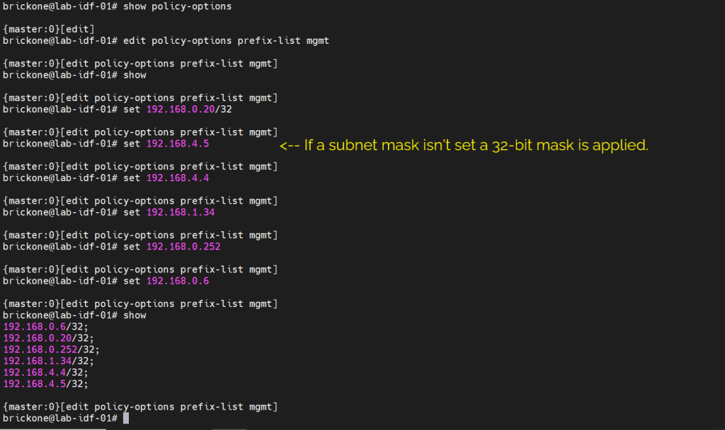
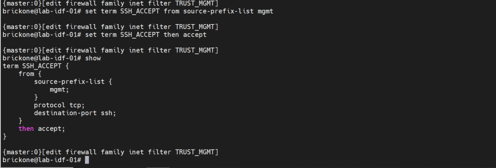
We will secure our device further by only allowing specific subnets or hosts to remotely access our device. On Juniper devices we will use a firewall filter to discriminate control plane traffic destined for the routing engine. We want to make sure we do not lock ourselves out of the device. As well as drop other traffic. At the end of all firewall filters, there is an implicit deny any. Juniper firewall filters use terms with from for matching, then for action statements. The steps are simple, we will configure our prefix list, apply it in a firewall filter configuration, along with our other match conditions. We will add an accept all at the end of the firewall filter. Then apply the firewall filter to our loopback interface.
#Create prefix-list
set policy-options prefix-list <name> <ip-address/prefix>
set firewall family <family> filter <name> term <term-name> from <match condition>
set firewall family <family> filter <name> term <term-name> then <action>
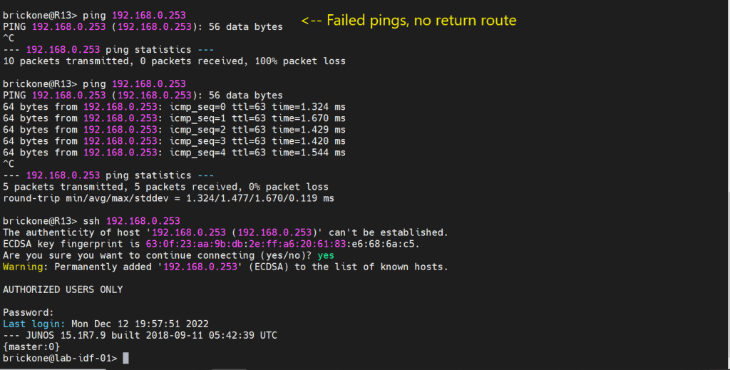
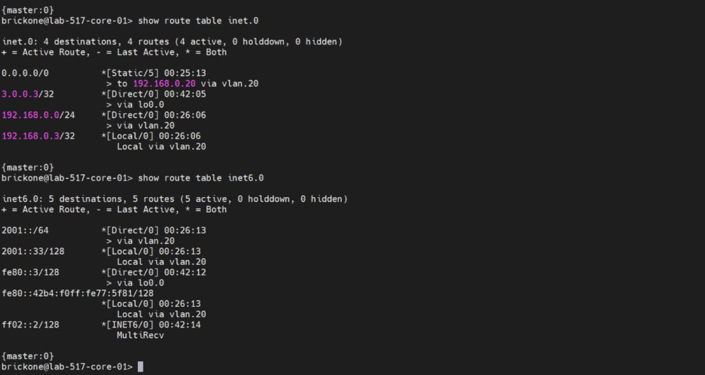
Before we configure our firewall filter, we need to configure connectivity. The only devices our switch can reach are directly connected devices. Since those will be the only routes in the routing table without administrative intervention. Because this device only has one path off the network. We will just configure a default route to our next-hop device.
#Static route configuration
set routing-options static route 0.0.0.0/0 next-hop <ip-address>
set routing-options static route 0/0 next-hop 192.168.0.20
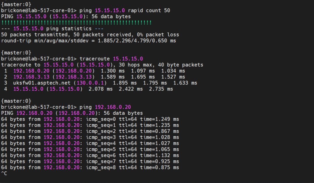
To verify that our switch is operating as we expected. We need to run show commands to verify reach-ability.
That’s all for now. Be wary when buying used gear, for labs it’s fine. My 48 port and 24 port ex4200’s dhcp snooping did not function at all. As always thank you for your time, and have a great day.
OSPF Router-id – 32-bit unique identifier of OSPF processes running on the router. OSPF process router-id selection criteria:
Use the router ID configured with router-id command in router process
Uses the highest non-shutdown ipv4 loopback address
Use the highest non-shutdown ipv4 configured interface address
-Multiple OSPF processes will skip addresses used by other OSPF processes on the device
-The RID configured with the router-id command will never change. A RID acquired by the process picking an interface address will change if the process restarts and the previous criteria has changed.
-The RID can be changed with either the router-id command, or altering interface addresses or states. Then restarting the OSPF process with the clear ip OSPF process exec command.
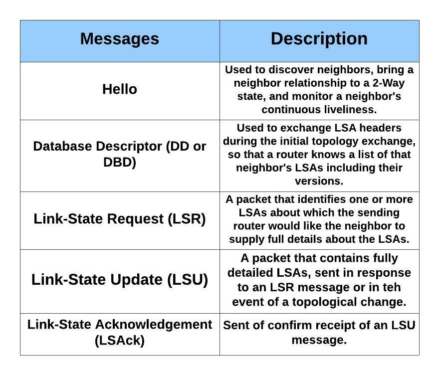
OSPF Messages
-LSAs are not OSPF messages. An LSA is a data structure, held inside a router’s LSDB and exchanged inside LSU messages.
OSPF Neighbor States
-Neighbors – Two routers that share a common data link and that exchange hello messages, and the hellos must match for certain parameters. (2-way/Drother)
-Adjacent (Fully Adjacent) – Two neighbors that have completed the process of fully exchanging DD and LSU packets directly between each other. (DR/BDR)
Discover other OSPF-speaking routers on common subnets
Check for agreement on selected configuration parameters
Verify bidirectional visibility between routers
Monitor health of the neighbors to react if the neighbor fails
Hellos are sourced from primary IP address on the enabled interface
-Hello Message Parameter Checks
Authentication must match
Subnet mask must match
Area must match
Area type must match
RIDs must be unique
Hello and Dead Timers must match
-MTU mismatch would affect database synchronization in the ExStart and Exchange phases. Routers can still become 2-Way neighbors successfully.
-Nat can affect this as well. If you run into issues check the range of your Nat statement.
Designated Router– DR/BDR
The DR/BDR are responsible for the flooding of LSUs. On a multi-access segment all routers are Fully adjacent with the DR & BDR. The DR also generates type 2 LSAs which represents the subnet and the router interfaces connected to the subnet.
Criteria for DR/BDR election:
Interface OSPF priority of 1-255 (0 excludes the router interface from participating in a DR/BDR election).
Highest router-id
-The DR/BDR position cannot be preempted. For instance, if a router is added to the segment with a higher router-id or priority. Current DR/BDR would have to be reset for another election to take place. If the DR goes down the BDR takes over. Then an election for a new BDR would be held.
– On multi-access segments, updates are sent to 224.0.0.6. Then the DR floods the LSUs with updated LSAs within the area. The LSU flooded by the DR serves as an acknowledgment to the original sending router that it was received. All routers except the originating router will acknowledge the flooded LSU with a unicast LSAck to the DR.
OSPF Network Types
-Broadcast Multi-access: Broadcast networks are capable of connection more than two devices. Broadcasts sent out one interface are capable of reaching all devices on the segment.
Router(config-if)# ip ospf network broadcast
-Non-Broadcast Multi-access: Frame Relay, ATM, and X.25 are considered non-broadcast multi-access, in that they can connect more than two devices, and broadcasts sent out one interface might not always be capable of reaching all the interfaces attached to a segment.
Router(config-if)# ip ospf network non-broadcast
-Point-to-Point: Allows only two devices to communicate. Point-to-Point circuits do not use ARP, and broadcast traffic does not become the limiting factor. Default for serial interfaces (HDLC or PPP encapsulation), GRE and Point-to-Point frame relay subinterfaces.
Router(config-if)# ip ospf network point-to-point
-Point-to-Multipoint: Not enabled by default on any medium. Supports hub-and-spoke connectivity while using the same IP subnet and is commonly found in frame relay and L2VPN topologies. Interfaces enabled for OSPF point-to-multipoint, add the interface’s IP to the LSDB as /32. Routes advertised out that interface will change the next-hop to the interfaces IP address.
Router(config-if)# ip ospf network point-to-multipoint
-Loopback: Can only be used on loopback interfaces. This network type indicates the address will always be advertised as a /32 prefix length. Changing the network type on the interface changes this behavior. The loopback network type cannot be manually assigned.
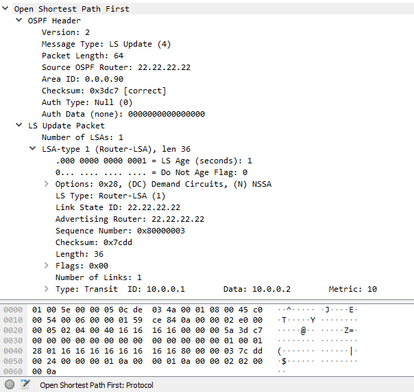
LSA TYPES
Router – One per router, per area, listing the router’s RID and all interface IP address in that area. Represents stub networks as well. Flooded only within its area of origin.
Network – One per transit network. Created by the DR on the subnet, and represents the subnet and the router interfaces connected to the subnet. Flooded only within it are of origin.
Net Summary – Created by ABRs to represent networks present in one are when being advertised into another are. Defines the subnets in the origin are, and cost, but no topology data. Flooded only within its area of origin; re-originated on ABRs.
ASBR Summary – Like a type 3 LSA, except it advertises a host route used to reach an ASBR. Flooded only within its area of origin; re-originated on ABRs.
AS External – Created by ASBRs for external routes injected into OSPF. Flooded to all regular areas.
Group Membership Defined for MOSPF, not supported by Cisco IOS.
NSSA External – Created by ASBRs inside an NSSA, instead of a type 5 LSA. Flooded only within its area of origin; converted to type 5 LSA on an ABR toward other areas.
External Attributes – Created by ASBRs during BGP-to-OSPF redistribution to preserve BGP attributes of redistributed networks. Not implemented in Cisco routers.
9-11. Opaque – Used as generic LSAs to allow for easy future extension of OSPF; for example, type 10 has been adapted for MPLS traffic engineering. These LSAs have different flooding scope: Type 9 has link-local flooding scope, type 10 has area-local flooding scope, type 11 has autonomous system flooding scope equivalent to the flooding scope of type 5 LSAs ) not flooded into stubby areas and NSSAs).
Router Types:
ABR: Arouter that has one interface in area 0 and other interfaces in non-zero areas. The ABR can filter routes, as well as summarize routes. Routers in an area have a complete view of the area. As they have identical LSDBs for that area. The ABR is responsible for flooding type 3 LSAs into the area.Two important rules in OSPF ABR functionality:
Only intra-area routes are translated into type 3 LSAs and flooded into the backbone area. Both intra-area and inter-area routes from the backbone are translated into type 3 LSAs, then flooded to non-backbone areas.
When an ABR runs SPF algorithm it ignores all type 3 LSAs received from non-backbone areas. This ensures that an ABR does not traverse a non-backbone area to reach a network that is located in the backbone or in some other non-backbone area.
ASBR: A router that injects routes originating outside the OSPF domain. ASBRs are also a point of filtering and summarization for injected routes. A router can be both an ASBR and ABR. Ex- A router injects a default route. (In normal areas, an injected default route is a type 5 LSA)
Area Types:
Normal Area: Allows the flooding of all LSA types.
Backbone Area: A special area that all ABRs must connect to. Type 3 LSAs must pass through this area to be accepted by a non-originating ABR.
Stub Area: A area the does not allow the propagation of type 5 LSAs. A default route is injected as a type 3 LSA by the ABR.
Totally Stubby Area: A area that does not allow the propagation of type 3, 4, and 5 LSAs. Only exception is the default route injected by the ABR as a type 3 LSA.
NSSA Area: A area that does not allow type 5 LSAs. External routes are injected as type 7 LSAs. No default route is injected without additional configuration. Default route injected is an type 7 LSA. Area <#> nssa Default-information originate
Totally NSSA Area: A area that does not allow type 3&5 LSAs. External routes are injected as type 7 LSAs. A default route is injected as a type 3 LSA by the ABR.
Authentication:
OSPF supports four types of authentication:
None: no authentication used
Clear text: clear text passwords used
MD5: Uses MD5 algorithm to hash password
SHA: Uses SHA algorithm with key-chain to hash password
Note: IOS 15.4(1) supports the extended SHA-HMAC (RFC 5709)
Default-Route:
The OSPF router command default-information originate will propagate a default route through the OSPF domain. Without the keyword always, a default route must be present in the routing table.
The default route is advertised as an external type-2.
Path Preference:
OSPF uses cost, reached by calculating bandwidth along a path. That is the primary decision in factoring the shortest path. As a loop prevention feature, OSPF also uses these criteria for path preference. Listed from most preferred to least:
Intra-area routes ( routes learned within the area )
Inter-area routes ( routes learned from another area)
External routes type-1 & type 2 ( routes redistributed from another routing domain)
NSSA routes type-1 & type 2 ( routes redistributed from NSSA area )
These path preferences do not account for cost.
Filtering:
Since OSPF is a link state protocol, all LSDB’s in an area have to be identical. A type 3 LSA can be filtered at the ABR, type 5 or type 7 can be filtered at the ASBR. Filtering on the local router is limited to the routing table.
-Note: To filter type 5 or 7 LSA’s not at the ASBR. You would need to use redistribution and filter the routes with a route-map. An example of this would be filtering a default route.
Summarizing:
Summarizing routes is also accomplished at the ABR & ASBR’s, which also allows for the non advertisement of routes. The biggest advantage of summarizing is smaller routing tables. Allowing for faster SPF calculations. The metric can either be designated or will be the lowest metric of the component routes.
The last note to bring up is that all areas must connect to area 0. All traffic must traverse through area 0. So when creating an OSPF topology this must be taken into account. Using virtual links or GRE tunnels are band aid solutions to temporarily resolve connectivity issues caused by improper design.
This post is about using an Ubuntu install as a router. I will be using it as a VM in Hyper-V ( 8gb ram 6 cores 40gb hdd) for a home router. The configuration is straightforward. I will post links for pertinent content.
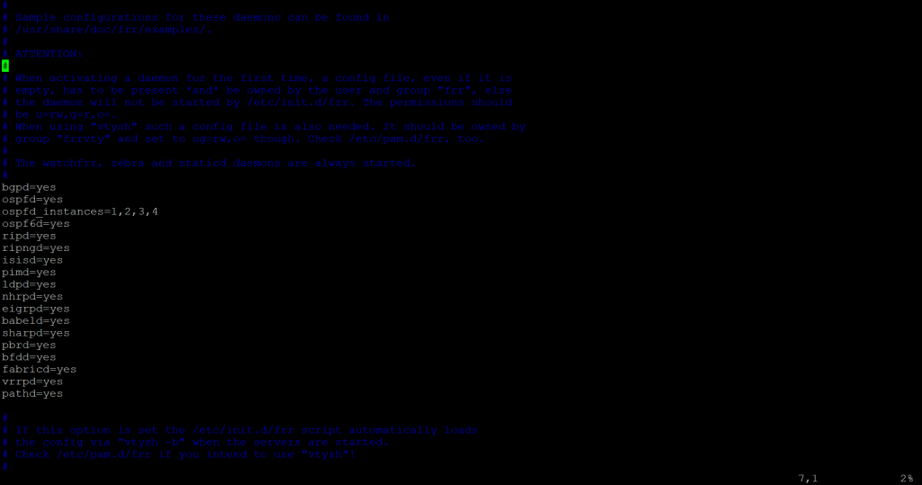
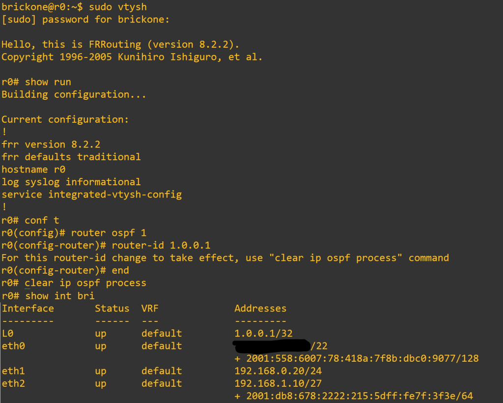
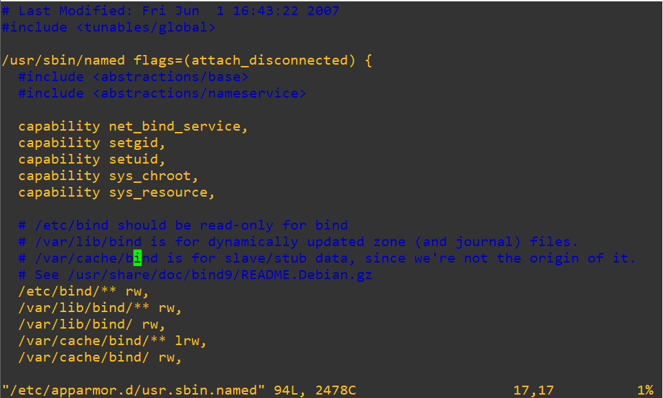
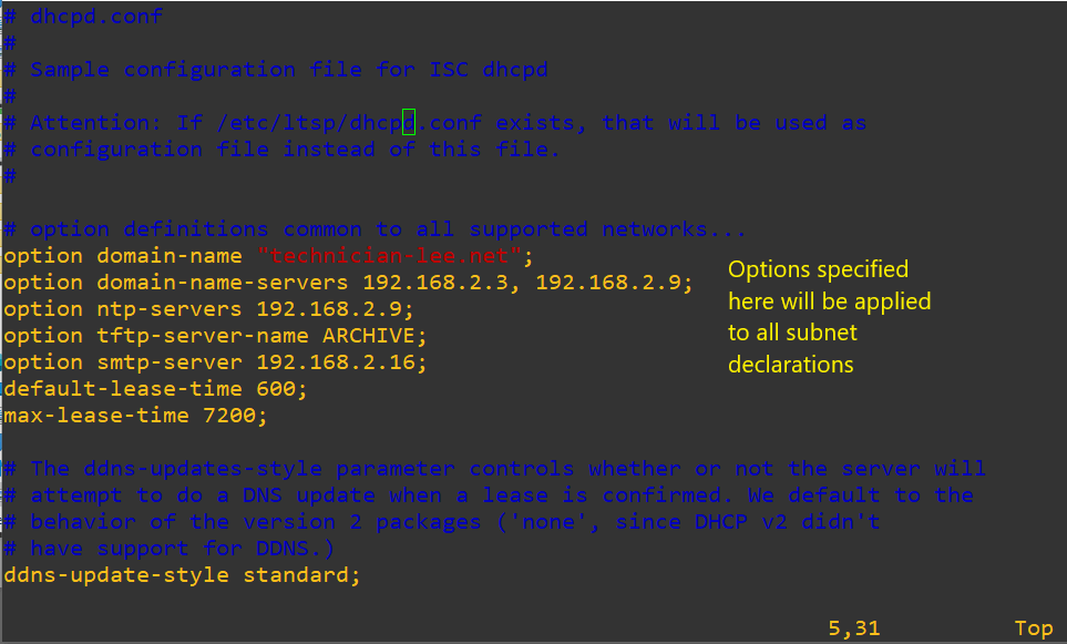
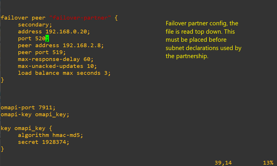
Once we have the operating system installed. We need to make a few changes. I like to use Ubuntu routers in my lab. We will configure a loopback, isc-dhcp-server, Bind, install free range routing, set up NAT and port forwarding. It is ideal to add a public key to the server for more secure SSH logins. I bring down a key from GitHub during installation.
#Create script to create loopback on system startup. The loopback created will not be persistent through system restarts. We will also add the configuration to netplan.
#Create script – you can put it whatever directory you like. For simplicity we are putting it in the #home folder. Typing in pwd and pressing enter should give you your current working directory.
#You can also place the scripts in a directory listed in the PATH environment variable. You can also add a path by editing the /etc/profile for global or .bashrc for user specific. add export PATH=”/path:$PATH” at the bottom of the file.
~ means home directory
brickone@r0:~$ pwd
/home/brickone
sudo touch L0.sh
sudo vi L0.sh or nano L0.sh <- You can use whichever editor you like
#!/bin/sh
ip link add name L0 type dummy <– Creates dummy interface
ip link set L0 up <– Puts dummy interface in up state
:wq (vim) or ctrl+w ctrl+x (nano)
Sudo chmod 0755 L0.sh <– assign proper permissions, if you forget this step service will show failed. Check failed services with:
Systemctl –failed
sudo touch /etc/systemd/system/L0.service <– Create service file
sudo vi /etc/systemd/system/L0.service <– Edit service file
sudo systemctl start L0 <– Start our newly created service
sudo systemctl enable L0 <– Enable the service to start on system startup
# We can also run the script now if you don’t want to wait for a restart.
Sudo bash L0.sh
# edit netplan to add address to L0. Depending on your interface setup your file may differ. I am # going off the setup of DHCP client outside interface. Pressing tab to autocomplete file names # will assist you in finding your netplan file. For the isc-dhcp-server we need a interface in each # subnet we plan to serve. If you only plan to serve one subnet, you will be fine with just one # inside interface. If you plan on service multiple subnets, it will depend on your setup.
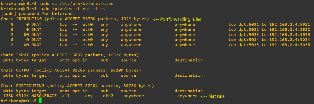
Now we will setup our NAT and if needed port forwarding. I say only if needed because ideally if you just want to access resources on your private network remotely a VPN would be a more secure option. But port forwarding is fine, let’s just be mindful of the ports we are opening and why. We will also need to make another script for a router to work.
# First let’s add the needed configuration changes
Sudo vi /etc/ufw/sysctl.conf
# Uncomment this to allow this host to route packets between interfaces
net/ipv4/ip_forward=1
net/ipv6/conf/default/forwarding=1 <– Optional
net/ipv6/conf/all/forwarding=1 <– Optional
sudo vi /etc/default/ufw
# Set the default forward policy to ACCEPT, DROP or REJECT. Please note that
# if you change this you will most likely want to adjust your rules
DEFAULT_FORWARD_POLICY=”ACCEPT”
# Now to add our rules, we will need the name of the outside interface
Sudo vi /etc/ufw/before.rules
# NAT table rules
*nat
:PREROUTING ACCEPT [0:0]
:POSTROUTING ACCEPT [0:0]
-F <– clear table when reloading, otherwise there will be duplicate rules
# Port Forwarding
-A PREROUTING -i eth0 -p tcp –dport 22 -j DNAT –to-destination 192.168.1.10 <– change to your needs
# Forward traffic through eth0 – Change to match you outside-interface
-A POSTROUTING -s 192.168.1.0/24 -o eth0 -j MASQUERADE
# -s 0.0.0.0/0 means any, you can specify a specific subnet or host.
# don’t delete the ‘COMMIT’ line or these nat table rules won’t
# be processed
COMMIT
# to load rules
# the firewall needs to be reloaded after changes and reboots.
# After you verify connectivity, the next steps are super optional. You can run these services on # the same box or other boxes. However you do it is fine.
# We do need to open some ports up. How specific you are is up to you
Sudo cp db.empty forward.db ß Name must match what you put as the file for Zone you added in named.conf.local. For example my file is called forward.tech-lee.net.db
Sudo vi forward.db
; zone file for your domain
$TTL 86400
$ORIGIN your domain
@ IN SOA server.yourdomain. email.yourdomain. (
2021070330 ; Serial ß needs to be incremented when changes are made
604800 ; Refresh
86400 ; Retry
2419200 ; Expire
86400 ) ; Negative Cache TTL
; Name server for this domain
@ IN NS server.yourdomain. <– your dns server your are creating this on
IN NS secondary-server.yourdomain. <– other dns servers in your domain
; Mail server for this domain. A small number (10) indicators higher priority
; A records host records for ipv4
DNS-PRIMARY IN A 192.168.2.5
DNS-SECONDARY IN A 192.168.2.6
R0 IN A 10.0.0.2
R0-1 IN A 192.168.3.254
R1 IN A 192.168.0.1
R4 IN A 192.168.3.2
R5 IN A 192.168.4.2
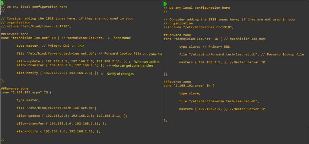
# Now the reverse zone. You need a different reverse zone for each subnet.
Sudo cp db.127 reverse.db
Sudo vi reverse.db
$TTL 86400
$ORIGIN Zone name.
@ IN SOA server.yourdomain. server.yourdomain. (
2021070322 ; Serial
604800 ; Refresh
86400 ; Retry
2419200 ; Expire
86400 ) ; Negative Cache TTL
; Name server for this domain
@ IN NS server.yourdomain.
IN NS seconry-server.yourdomain.
; PTR Records
12.20 IN PTR MLSW1.technician-lee.net. ; 192.168.0.2
100.100 IN PTR R1.technician-lee.net ; 192.168.0.1
101.101 IN PTR MLSW2.technician-lee.net ; 192.168.0.6
# now we need to reload and enable
Sudo systemctl start named <– if it isn’t started
Sudo systemctl restart named <– if it was already started
Sudo systemctl enable named <– So it will start on boot if the slave server has trouble writing files check the permission in the file below
sudo ntpdate your-network-ntp-server <– sync clock with ntp server
sudo timedatectl set-ntp off
sudo apt install ntp -y
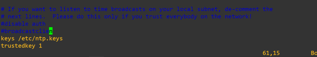
sudo vi /etc/ntp.conf
sudo vi /etc/ntp.keys
sudo systemctl restart ntp
ntpq -p
Now you have an awesome home router. There will be links at the bottom for additional information and some idea of performance. Thank you for your time.
One of the coolest moments in troubleshooting is when the device tells you what is happening.
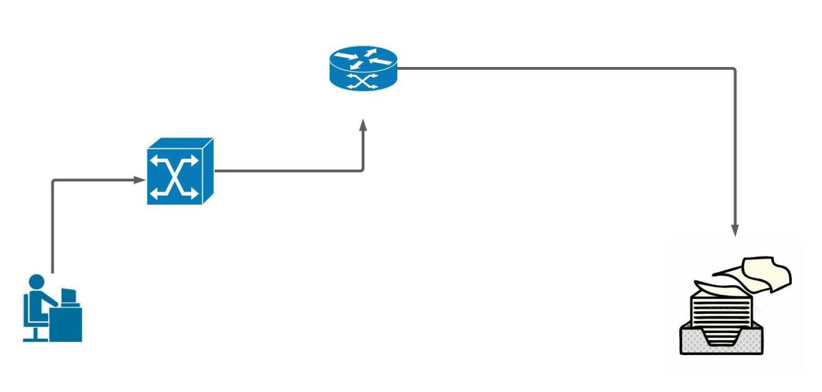
Syslog messages let us know events transpiring on our Cisco devices. We can store logs in the device ram, an external server, or on non-volatile storage on the device.
Defaults:
By default all logging is sent to the console port
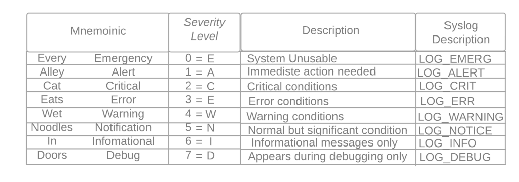
Default logging level debugging (7) for console, monitor, and buffer.
Trap logging defaults to informational (6)
Buffer logging default size 8192, once filled older messages are deleted.
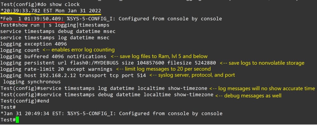
Service timestamps log|debug datetime – is the default for log messages. Log messages time will match UTC time.
Logging rate-limit default is 10 log messages per second.
If nothing different is specified UDP port 514 is used for host logging.
Console logging – all messages are sent to the console port.
Monitor logging- messages are displayed on the VTY lines of the device.
Buffered logging – stores the log messages using a circular buffer in the devices ram.
Exception logging – The main purpose of it is to restrict or disable the amount of buffered log sent to the console on a system crash
Persistent logging – stores the log messages from ram buffer to devices flash disk
Embedded Syslog Manager (ESM) uses syslog filter modules to process system logging messages. Syslog filter modules are scripts written in the Tool Command Language (Tcl) stored in local system memory or on a remote file server.
Host logging (syslog) – forwards log messages to an external syslog server.
SNMP logging – uses SNMP traps to send log messages to an external SNMP server.
For proper logging, it is best practice to configure the device’s clock. It is recommended to use ntp.
Configuration to allow logging to all three, ram, server, and flash.
Notes – Using buffered or persistent logging takes away system resources. I should be used cautiously. Verify connectivity to server, port and protocol. Verify service timestamps and ntp settings when facing logging time inconsistencies.
Conditional Debug:
Making a debug as tuned as possible is awesome. Here is an example.
Conditions are turned on with the command
Router# debug condition < parameter>
Ex- Router# debug condition ip 192.168.0.1
Router# debug condition interface g0/1
Router# show debug <– view debugs and conditions
Debugs are removed with no debug condition <#>
Ex- Router# no debug condition 1
When removing the last debug condition you will be prompted.
Debugs without conditions.
I would experiment with this in a lab on the same IOS version you plan to use in a different environment. Turning on debugs is taking the packets from the data plane and sending it to the control plane. You can brick a device or cause it to restart. Not good for professional environments.
As always thank you for your time.
-Notes
By default, the console port processes all debug output, even when it is logging messages to an internal buffer or when it is sending the debug output to a vty or aux port. A router will prioritize console output; therfore sending a significant amount of debug output to the console port can cause the router to hang. To prevent this from occurring, you should issue the no logging console command unless you are actively logging to the console port. In addition, if you must capture large amounts of debug output, you should always send the output to a vty port. to the aux port, or to an internal logging buffer.
The no logging on command will cause debug messages to appear only on the console, thereby disabling logging to the vty port, aux port and internal buffers.
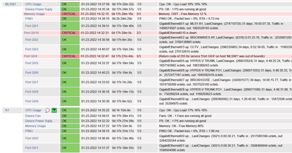
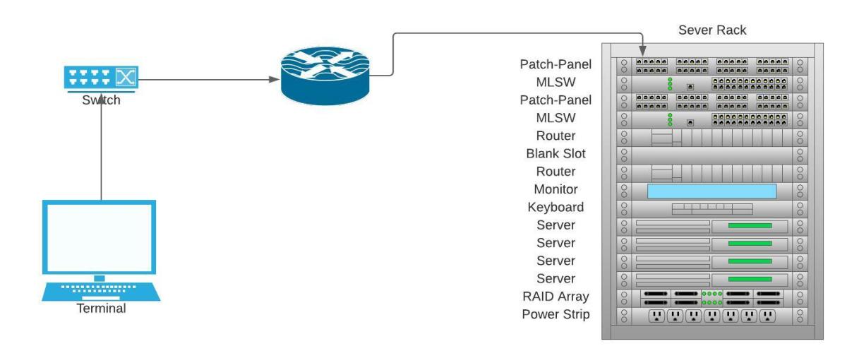
We will be installing Nagios to monitor our Cisco devices via SNMP . The device config is brief compared to the server config. I will accompany config with screenshots, as well as links at the bottom. I will be using a Ubuntu 20.04 , Cisco 3560 15.2(2) , and Cisco 194115.0(1) .
Pre-requisites:
A Cisco device (physical or virtual) to configure and poll
Not so much a must, but having a nice amount of free time to do projects helps. Troubleshooting can pop up, or you could just want to delve further into the subject. I also suggest note taking, whichever form.
Cisco Device Configuration:
-V2c
Router(config)# ip access-list standard <ACL-Name>
Router(config-std-acl)#permit <server ip address>
Router(config)# snmp-server community <chosen community string> RO <ACL-Name>
Router(config)# snmp-server location <location>
Router(config)# snmp-server contact <contact>
Router(config)# ip domain-name <domain-name>
Router(config)# snmp-server ifindex persist <– Router keeps same interface index even after reboot.
-v3
Router(config)#snmp-server view VIEW1 internet included <– Creates VIEW1 with access to everything
Router(config)#snmp-server group GROUP1 v3 priv read VIEW1 write VIEW1<– Create v3 group assigned view VIEW1 Router(config)#snmp-server user bob GROUP1 v3 auth sha cisco123 priv aes 128 juniper1 <– Creates user bob nested in GROUP1, authentication hashing algorithm is sha. Authentication password is cisco123. Encryption algorithm is aes 128 with password juniper1
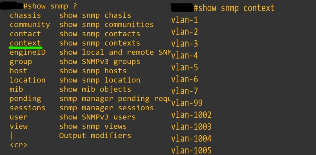
Router(config)#snmp-server group GROUP1 v3 auth context vlan- match prefix <– You must use contexts to get per-VLAN data from the BRIDGE-MIB with SNMPv3.Not all the IOS switches support this. In general, if the device supports the “show snmp context” command, contexts will work. If not, an upgrade is needed. However, some switches (e.g. 2950 series) will never support SNMPv3 contexts. You must use v1/v2c with these switches.
Router(config)# snmp-server ifindex persist <– Router keeps same interface index even after reboot.
Device needs context configuration if this command is present.
The error I experienced with no context configured.
The result we want from snmpwalk command. Ctrl+c to end the massive stream of text.
Now the Nagios Server. I thought text would be more appropriate for copy and paste. I know we all get enough typing practice.
sudo apt update -Install Dependencies sudo apt install -y autoconf bc gawk dc build-essential gcc libc6 make wget unzip apache2 php libapache2-mod-php libgd-dev libmcrypt-dev make libssl-dev snmp libnet-snmp-perl gettext -Navigate to home directory cd ~/ -Download Nagios Core 4.4.6 sudo wget https://github.com/NagiosEnterprises/nagioscore/archive/nagios-4.4.6.tar.gz -Extract the Nagios Package and navigate to extracted Nagios Directory sudo tar -xf nagios-4.4.6.tar.gz cd nagioscore-*/ -Compile and Install Nagios sudo ./configure –with-httpd-conf=/etc/apache2/sites-enabled sudo make all -Create the Nadios user and group, and add the ‘www-data’ Apache user to the ‘nagios’ group sudo make install-groups-users sudo make install-commandmodeudo usermod -a -G nagios www-data -Install Nagios binaries, service daemon script, and the command mode. sudo make install sudo make install-daemoninit sudo make install-commandmode -Install the sample script configuration sudo make install-config -Install the Apache configuration for Nadios and activate the mod_rewrite and mode_cgi modules. sudo make install-webconf sudo a2enmod rewrite cgi -Restart Apache service sudo systemctl restart apache2
-Create nagiosadmin user. This is the user we will use to login to web interface. sudo htpasswd -c /usr/local/nagios/etc/htpasswd.users nagiosadmin
-Setup UFW Firewall sudo ufw allow apache sudo ufw allow ssh sudo ufw enable y sudo ufw status numbered -Install Nagios Plugins and NRPE Plugin sudo apt install monitoring-plugins nagios-nrpe-plugin -Once installation completes go to the nagios installation directory /usr/local/nagios/etc cd /usr/local/nagios/etc sudo mkdir -p cisco/{remotehosts,commands,servicegroups,hostgroups} -Now we need to edit Nagios config to load our config directory sudo vi nagios.cfg -add line cfg_dir=/usr/local/nagios/etc/cisco :wq save and close
sudo apt install tree
-The two plugins downloaded at the beginning must be placed into the /usr/local/nagios/libexec dir
-Let’s create a hostgroup for out cisco devices
cd /usr/local/nagios/cisco
sudo vi hostgroups/cisco-devices.cfg
– add this text
define hostgroup{ hostgroup_name cisco-devices alias Cisco_devices }
-save and close
-Then we need to define our hosts and services
sudo vi remotehosts/<hostname>.cfg
define service{ use generic-service host_name <hostname> service_description CPU Usage check_command check_cisco_switch!<community-string>!cpu!60!70 servicegroups cpu-usage }
define service{ use generic-service host_name <hostname> service_description Device Fan check_command check_cisco_switch!<community-string>!fan servicegroups device-fan } define service{ use generic-service host_name <hostname> service_description Device Power Suply check_command check_cisco_switch!<community-string>!ps servicegroups device-powersupply }
define service{ use generic-service host_name <hostname> service_description Port G0/0 check_command check_cisco_int!<community-string>!G0/0 servicegroups cisco-interfacestatus }
define service{ use generic-service host_name <hostname> service_description Port G0/1 check_command check_cisco_int!<community-string>!G0/1 servicegroups cisco-interfacestatus }
-You can add and remove services as you like, just remember the commands. Example is my 3560 doesn’t have a fans, so I removed that service.
-Next service groups
sudo vi servicegroups/cisco-services.cfg
define servicegroup{ servicegroup_name memory-usage alias Memory Usage }
define servicegroup{ servicegroup_name cpu-usage alias CPU Usage }
define servicegroup{ servicegroup_name device-fan alias Device Fan }
define servicegroup{ servicegroup_name device-powersupply alias Device Power Supply }
define servicegroup{ servicegroup_name cisco-interfacestatus alias Cisco Interface Status }
As always thank you for your time. There is so much more to learn about device management. Nagios isn’t perfect but projects like this deal with quite a bit of troubleshooting. I find them great to learn about things you would of otherwise just skimmed by.
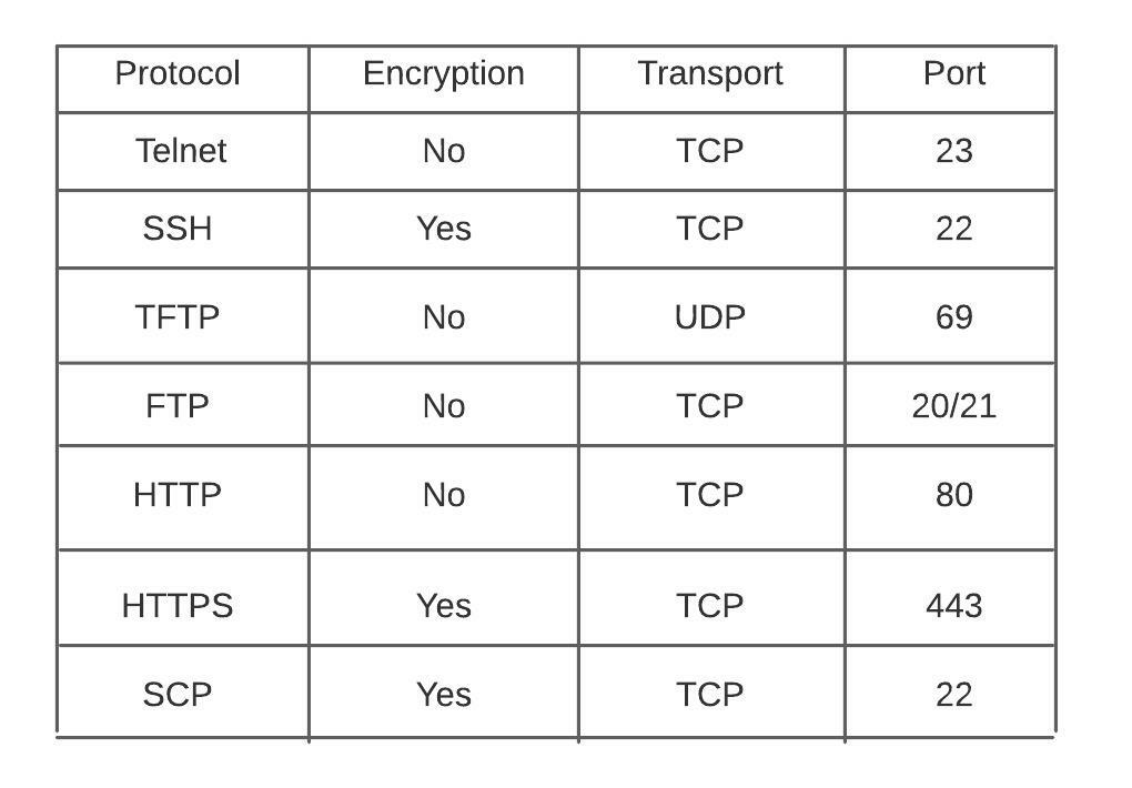
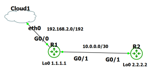
There are multiple protocols for device management on the Cisco platform. There is even a protocol for transferring images through the console cable (xmodem). In this post we will go over examples of utilizing these protocols. The goal is to understand our options when we want to access or transfer files to or from our devices. I will be using my usual setup of GNS3 with a connection to my network.
Telnet Telnet utility allows users to test connectivity to remote machines and issue commands through the use of a keyboard. It can be used to test open TCP ports on a device. It requires a password be set on the line to login. All communication is in clear text. telnet towel.blinkenlights.nl <– found this
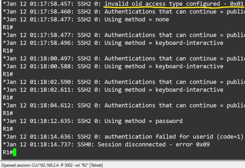
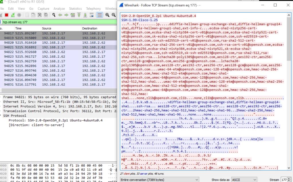
SSH
Used for secure device access, as well as file transfer. Prerequisites: Must configure hostname. Must have username and password configured. Must have domain name configured on device. Used in key generation. Must have keys generated for secure connection Must enable transport support on vty lines. Router#ssh -l <username> -c <cipher> -m <hmac algorithm> -v <version> -p <port> Login local or AAA configured on vty lines ( AAA by default applies login local to vty lines.)
Properly configured
debug ip ssh detail – line vty 0 4 configured with login cmd and password.
File Transfer To copy files to/from your cisco device you would use the copy command. Router#copy <source> <destination>
TFTP Trivial file transfer protocol is a simplified version of ftp. It does not require authentication, no encryption is supported. tftp should only be used int your private network, not on any outside facing interfaces. A path is configured, devices can be pointed to it by your DHCP server if needed. They are extremely easy to setup. Files can be transferred with either the copy command or snmp. Successful transfer are displayed with a ! . As far as Cisco device’s support as a tftp server, it is limited. It can only serve files for download. You cannot use this feature to upload files into the serving router’s local flash.
SCP Prerequisites: SSH enabled – scp utilizes ssh to securely transfer files AAA new-model
AAA authentication and authorization properly configured ip scp server enable
HTTP(S)
HTTP and HTTP can be used to copy files to/from remote server. HTTP uses TCP port 80 unencrypted, HTTPS uses TCP port 443 encrypted. The HTTP copy operation can use the embedded HTTPS client for HTTP Secure transfers, providing secure and authenticated file transfers within the context of a public key infrastructure (PKI).
FTP
FTP is a file transfer protocol, it has a secure version called sFTP. There are a plethora of servers available to deploy. On the client side we just need to present the server address, username and password.
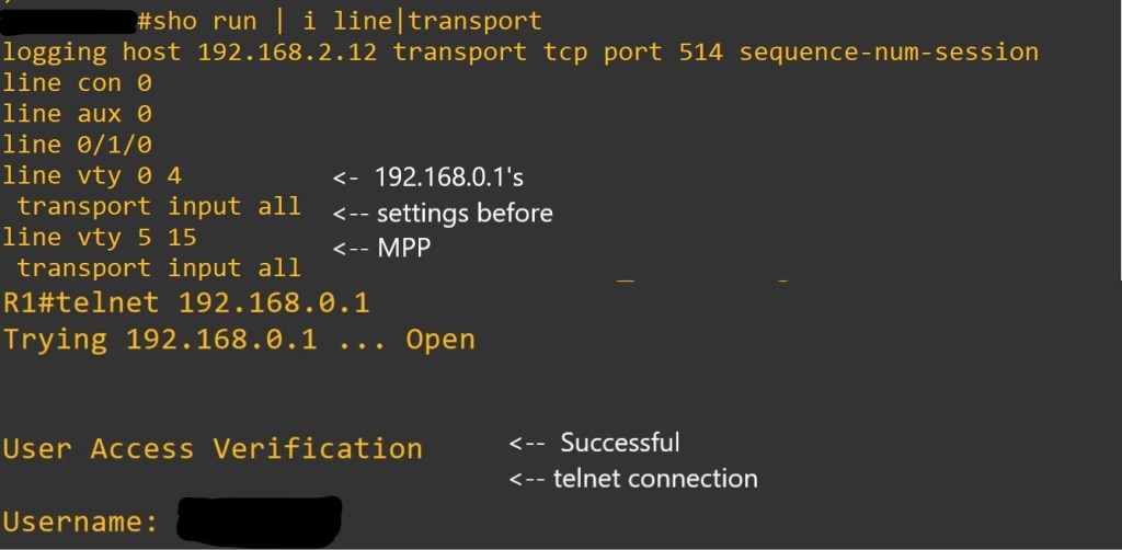
MPP
Management plane policing is used to restrict on which interface, as well as which protocol packets the router will accept. It reduces the amount of ACLs needed for management traffic control. MPP silently drops packets and does not forward them to the cpu.
As always thank you for your time. Links will be at the bottom for your pursuit.
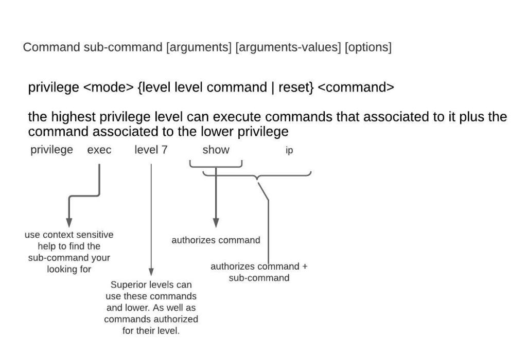
Managing device authorization has more tools than I previously understood. Using a server is a great option but may not be for your situation. I will do a brief overview of setting up a router with privilege levels and views. I will try to keep the post digestible, while covering a nice amount of the topic. This will be brief explanation of configuration.
Configuration:
Privilege level 15 – upon login is at the privileged level 15 exec mode. No restriction on commands.
Privilege level 1 — Normal level on Telnet; includes all user-level commands at the router> prompt.
Login – configured line requires a configured password, will be met with error “Login required, password not set”
Logging synchronous – is used to synchronize unsolicited messages and debug output with solicited Cisco IOS Software output. It is NOT a default. Exec-timeout 10 0 – by default, an IOS device will disconnect a console or VTY user after 10 minutes of inactivity. You can specify a different inactivity timer using the exec-timeout MINUTES SECONDS line mode command.
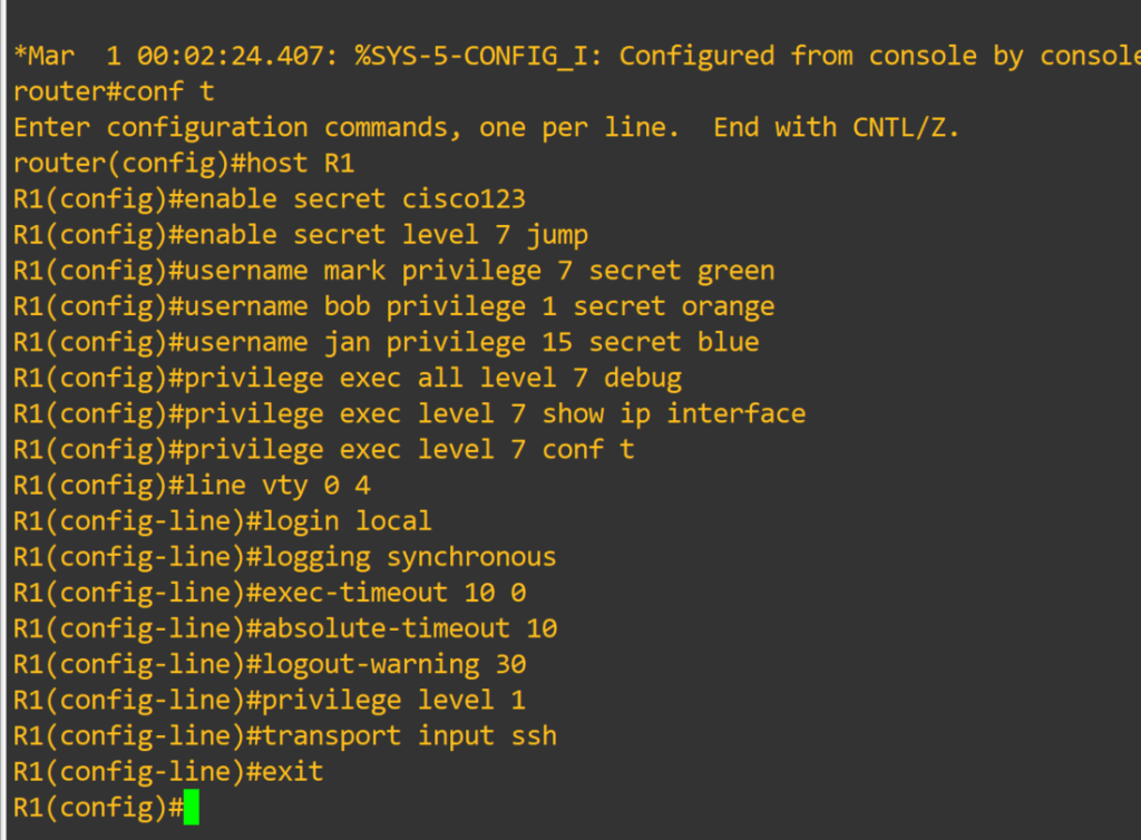
Router#configure terminal <–you can create system-wide resources for various system service, configure global behaviors, and enter specialized configuration modes.
Router(config)#host R1 <– changes device hostname
R1(config)#enable secret cisco123 <– is a command that allows setting a local password to control access to various privilege levels in global configuration mode. If you don’t specify a level it assumes level 15
R1(config)#enable secret level 7 jump
R1(config)#username mark privilege 7 secret green
R1(config)#username bob privilege 1 secret orange <– creates user with MD5 encrypted password. User will login at privilege level 1
R1(config)#username jan privilege 15 secret blue
R1(config)#privilege exec level 7 show running-config
R1(config)#privilege exec all level 7 debug <– This lowers the required privilege level to run all the debug commands to level 7. The all option includes all sub-commands
R1(config)#privilege exec level 7 show ip interface
R1(config)#privilege exec level 7 conf t
R1(config)#privilege interface all level 7 ip
R1(config)#line vty 0 4 <– Range of line to configure. Configuring individual lines is not recommended.
R1(config-line)#login local <– Login using local user database
R1(config-line)#logging synchronous
R1(config-line)#exec-timeout 10 0
R1(config-line)#absolute-timeout 10 <– terminates EXEC session after the specified timeout has expired in minutes
R1(config-line)#logout-warning 30 <– logout warning in seconds
R1(config-line)#privilege level 1 <– sets the level user will log into, default for vty lines is 1
R1(config-line)#transport input ssh <– allowed method to access vty lines
R1(config-line)#exit
R1(config)#line con 0
R1(config-line)#exec-timeout 30 0
R1(config-line)#privilege level 1 <– default for console line is 15
R1(config)#no ip domain lookup <– disables dns lookup
R1(config)#crypto key generate rsa <– generates rsa keys used for ssh
R1(config)#interface fastEthernet 0/0 <– interface to configure
R1(config-if)#ip add 10.0.0.1 255.255.255.252 <– IPv4 address assigned to interface
R1(config-if)#no shutdown <– Interfaces are down by default, brings them up
R1(config-if)#exit
R1(config)#interface loopback 0 <– virtual interface that is always up
R1(config-if)#ip add 1.1.1.1 255.255.255.255
R1(config-if)#exit
There is much to be desired as far as granularity goes for command authorization. That is where our next config comes in.
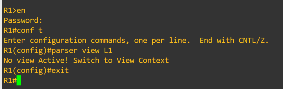
Role-based CLI views provide granular control over administration.
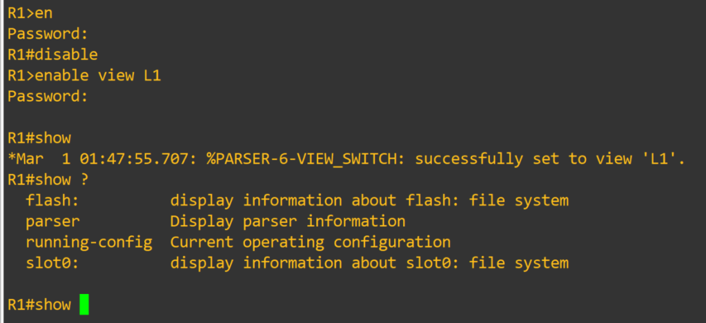
Root View – equivalent to level 15 privilege, used to administer any view. The difference between a user who has level 15 privileges, and a root view user is that a root view user can configure a new view and add or remove commands from the view. Views are limited to the commands that have been added by the root view.
R1#enable view <– password is level 15 enable password
R1#conf t
R1(config)#aaa new-model
R1(config)#parser view <L1> <– creates view
R1(config-view)#secret <jump1> <– assigns password to view
R1(config-view)#commands interface include ip add dhcp
R1(config-view)#commands interface include no shut
R1(config-view)#commands configure include interface
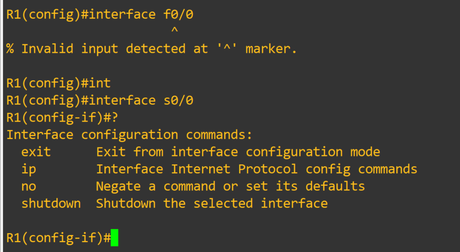
R1(config-view)#commands exec include configure terminal
R1(config-view)#commands configure include interface s0/0
R1(config-view)#commands exec include show running-config
R1(config-view)#commands exec exclude show startup-config
R1(config-view)#exit
R1(config)#exit R1#disable <– exit enable view mode, then use enable view <L1> to enter in view
Just amazing, I will links at the bottom for sources. This is something worth spending some time experimenting with. I fell in love with views when I realized I couldn’t limit certain commands with privilege levels. I could see these techniques utilized in a small environment, as long as proper documentation and change control were in place.
In this post I will be going over the Radius configuration. A lot of it mirrors the Tacacs+ configuration. I will not go through server configuration. I only did that for Tacacs+ because of the limited options available. Radius has multiple options available, Windows Server NPS, Freeradius etc. Couple of key differences:
Radius uses UDP port 1812 for Authentication & Authorization.
UDP port 1813 for Accounting.
Supports EAP for 802.1x authentication
Cannot be used to authorize which cli commands can be executed or account cli commands
First things first.
– aaa new-model check list:
– enable secret <string>
– username algorithm-type < sha254 or scrypt> secret <string>
Router(config)#aaa authentication login default group radius local
Router(config)#aaa accounting network default start-stop group radius
Router(config)#aaa accounting system default start-stop group radius
The configuration is simple enough. A few things to discuss. For command authorization you have two options, Tacacs+ server or local configuration. The Tacacs+ server option is less of an administrative burden. The local option has plenty of documentation. I will leave links at the bottom of this post. Privilege levels can be assigned to users and enable passwords. In the case of Radius defining the user privilege dictates which exec mode they are greeted with when authenticated. It’s still extremely useful authentication server. It can be used with 802.11 as well as 802.1x.
Just like with the Tacacs+ configuration we want to make sure we define the server before attempting to add it to a group. Making sure the ports match on the server and the device. Here is a sample config of local command authorization.
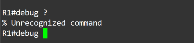
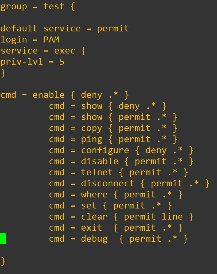
The debug command was not explicitly permitted, so it is not able to be used at privilege level 7. It’s a nice back up in case servers are unreachable, but I wouldn’t want local to be my only option.
Thank you for your time
-Notes
Use debug commands to assist troubleshooting configuration:
Debug aaa authentication
Debug aaa accounting
Debug radius accounting
Debug radius authentication
Use the test command to verify server functionality:
test aaa group radius server name <defined server> <username> <password> new-code
Authentication: Enables a user to be identified and verified prior to being granted access to a network devic and/or network services.
Authorization: Defines the access privileges and restrictions to be enforced for an authenticated user.
Accounting: Provides the ability to track and log user access, including user identities, start and stop times, and executed commands.
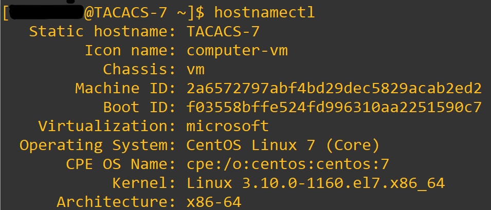
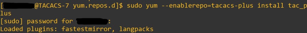
Tacacs+ – uses TCP port 49, open standard created by Cisco. It is mainly used for device access control. We will be installing it on Cent OS 7 and utilizing the service with a Cisco router.
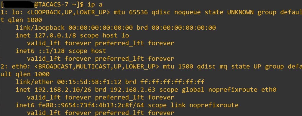
sudo firewall-cmd –get-zone-of-interface=eth0 <– Put your interface here, enter < ip a > at terminal
sudo firewall-cmd –get-icmptypes
sudo firewall-cmd –get-services
cd /usr/lib/firewalld/services/ ls <– to view services available
cd /etc/firewalld/services/
sudo cp /usr/lib/firewalld/services/ssh.xml /etc/firewalld/services/tac_plus.xmlcd /etc/firewalld/services/tac_plus.xml ^– used to copy ssh.xml to tac_plus.xml
sudo vi /etc/firewalld/services/tac_plus.xml <– edit service xml
You don’t need to change description. The protocol- TCP and port- 49 are a must. The name is very useful.
sudo firewall-cmd –reload
sudo firewall-cmd –state
firewall-cmd –get-active-zones
firewall-cmd –get-service
Once we verify the port is open, we will configure our device to connect.
The commands:
Router(config)#aaa new-model
– enables aaa on device. By default, lines will use login local until a default method list is defined or a user defined method list is applied to the lines. Best practice to make a user account before issuing this command. To lessen the likely hood of locking yourself out of device.
aaa new-model check list:
enable secret <string>
username algorithm-type < sha254 or scrypt> secret <string> <– may not be supported depending on your IOS version
username < username> secret <string>
crypto key generate rsa <– we want a key size of 1024 or above , then enter to defaults
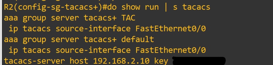
The servers need to be defined before being added to a group.
Theses are by default part of the Tacacs+ group of servers after being defined.
Router(config) aaa group server tacacs+ <TAC>
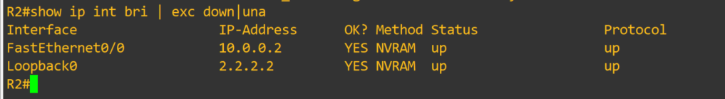
Router(config-sg-tacacs+)#server 192.168.2.10
Router(config-sg-tacacs+)#exit
Router(config)#aaa authentication login default group <TAC> Local
Default is the method list that will be called upon when the service needs to know which database to match against.
TAC is the user defined group that will be used first for authentication. Local is the local database on the device that will be used second if the first method cannot be contacted.
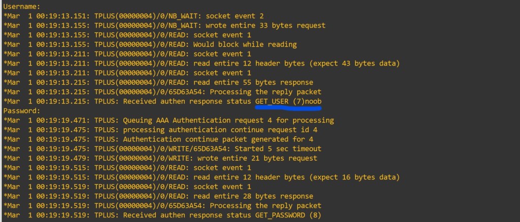
Since we used the default method list the lines should be good to go. To view what is happening lets enter in some debug commands.
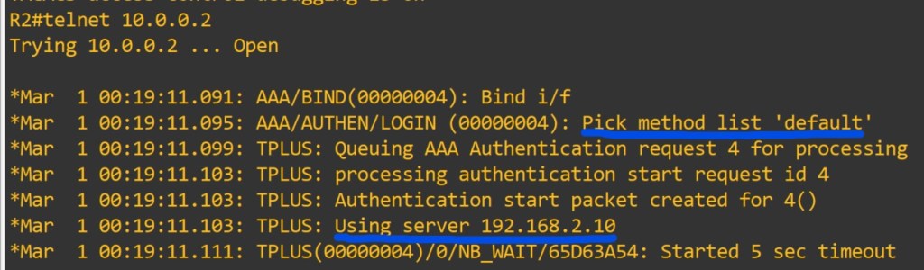
Router#debug aaa authentication
Router#debug aaa authorization Let’s try: I will use telnet to myself.
Debugs are super useful in troubleshooting as well as learning. Use with caution, they can cause a RPE (resume producing event).
This user shouldn’t be privilege lvl 15. It shows we didn’t define a method list for authorization.
AAA authorization exec enables EXEC shell authorization for all lines except the console line.
AAA authorization console – Authorization for the console is disabled by default to prevent inexperienced users from locking themselves out.
Privilege level 0 – includes disable, enable, exit, help and logout.
Privilege level 1 – also known as User Exec mode. No configuration changes.
Privilege level 2-14 – can be configured to provide customized access control. ( either local or on server)
When all the AAA servers are unreachable AAA command authorization might still be trying to reach the servers. This will prevent users from being able to execute any more commands. Safety measure use the if-authenticated method. Allows all commands to be authorized as long as the user has successfully authenticated locally.
Router(config)#aaa authorization exec default group tacacs+ if-authenticated
After entering that command, let’s test the functionality.
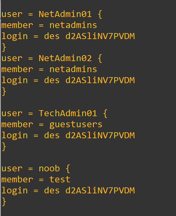
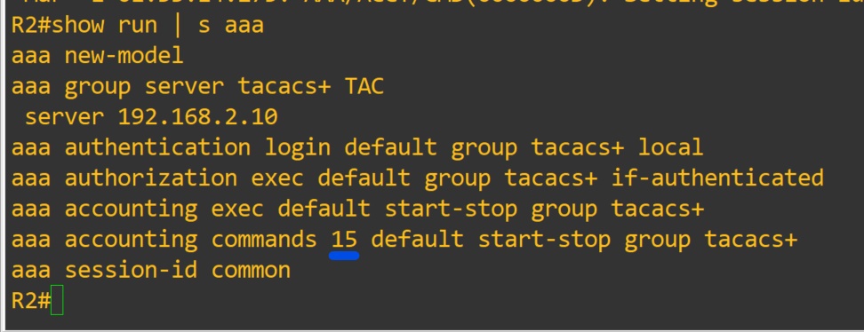
Since we defined allowed commands and privilege level to the group. Added the user to the group (on the server). We have restricted the users commands on the device from the server. We can also enable accounting very easily too.
Router(config)#aaa accounting commands 15 default start-stop group tacacs+
The log file location is in the tac_plus.conf file at the very top.
You have to define the privilege level you will be accounting.
Show commands:
show run | section username|aaa|line|tacacs
-NOTES
Do not allow the global enable password to be compromised. It will grant lvl 15 to users. Enable passwords for lower levels can be designated. Replace 15 with desired level. In a different post we will configure enable passwords of different levels. To utilize the enable passoword on the server. you would configure aaa authentication enable default group tacacs+
Troubleshooting Notes:
Check that server ip address is defined correctly on device.
Check that the secret matches on server and device
Check that you can connect to device via tcp port 49
c.1. You may have to install telnet
c.2. Telnet only works on tcp
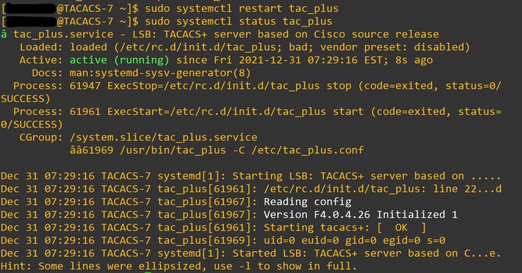
Sudo systemctl status tac_plus -l
Sudo journalctl -xe
aaa authorization config-commands is enabled with aaa authorization exec command
aaa authorization commands <priv level> { default | user defined list} – authorized all commands with the AAA server before executing them. Applied on a per-privilege level basis. A command authorization method list must be defined for every privilege level that requires command authorization.
If the aaa authorization commands level method command is enabled, all commands, including configuration commands, are authorized by authentication, authorization, and accounting (AAA) using the method specified. Because there are configuration commands that are identical to some EXEC-level commands, there can be some confusion in the authorization process. Using the no aaa authorization config-commands command stops the network access server from attempting configuration command authorization.
Examples
The following example specifies that TACACS+ authorization is run for level 15 commands and that AAA authorization of configuration commands is disabled:
aaa new-model
aaa authorization command 15 group tacacs+ none
no aaa authorization config-commands
If the aaa new-model command has been configured to enable the AAA access control model, the no aaa authorization console command is the default, and the authorization that is configured on the console line will always succeed. If you do not want the default, you need to configure the aaa authorization console command.
User defined method lists must be applied to the lines to be used by device. We used the default list in this lab. Verify the line is configured with sh run | s line