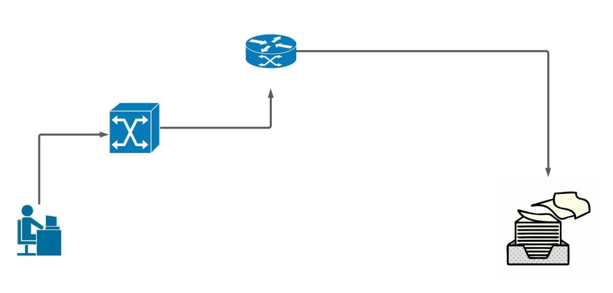
This is going to be a quick post about getting started with KVM. If you have used a type-1 hypervisor before, then you will be familiar with the topology used here. The adding of openvswitch is to allow trunk ports on our virtual switches. By default, most hypervisors only have access ports. To complete this setup you need a physical networking device that can do trunking (switch). Either a linux machine with a graphical desktop or windows machine with WSL installed. Two available ethernet ports on your computer. One connection for management. The other connection will be the vm trunk. I will be using Ubuntu 20.04. The hypervisor can be hosted on your server or ubuntu desktop. In this tutorial I’m using Ubuntu desktop 20.04.
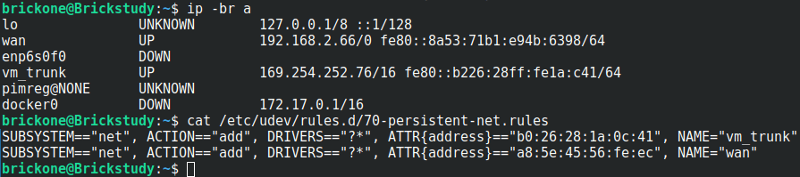
#Before we create the bridge, you should have an interface picked out. #
#Giving the interfaces a distinguishing name can assist with troubleshooting.
#You can create a text file in the /etc/udev/rules.d/ directory named #70-persistent-net.rules. The changes will not apply until you reboot the system.
#You only have to add the tagging to the bridge and interface once.
#The vms’s interface tag configuration will have to be applied again if there is a restart.
#We will make a #simple script to find our desired vm interface and give it the tags we want.
sudo ovs-vsctl set port br1 tag=99 ← Sets the vlan tag of the interface
sudo ovs-vsctl set port br1 trunks=[2-250]
# ^Sets the vlans on the trunk, can be a range as well as separated by commas
sudo ovs-vsctl set port br1 vlan_mode=native-untagged ← Sets the interface to use native vlan
#The bridge is down when created. We should bring the bridge up and #assign an address to it.
#The configured address should be in the subnet of the tag on the bridge.
#For me vlan 99 = 192.168.0.0/24
#The below commands will not persist after a reboot.
sudo ip addr add 192.168.0.6/24 dev br1
sudo ip link set br1 up
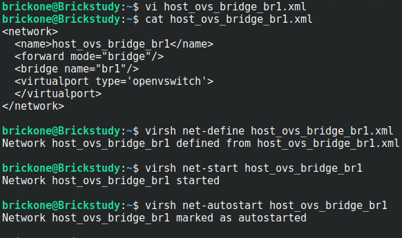
#The above commands import the bridge into KVM, start the bridge, then
#enable the bridge to start on system boot.
#You can now create a vm via the command line or the gui.
#We can open up virt-manager and start installing our first vm
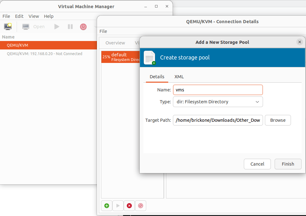
#Start by creating the storage pools. These are the locations of your vms and installation images.
#Double click the Qemu/KVM
click the green plus sign to create the storage pools
Verify in the Virtual Networks tab that our bridge is listed
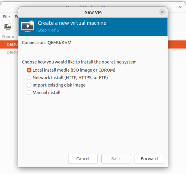
Click File> New Virtual Machine
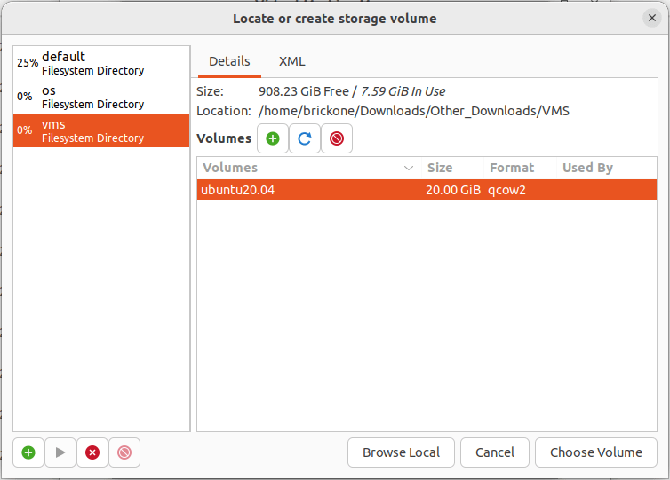
To install from an ISO file pick Local Install > Browse to the iso file on the configured storage pool. If you previously added the image to the folder. Click refresh, highlight your selection and click choose volume.
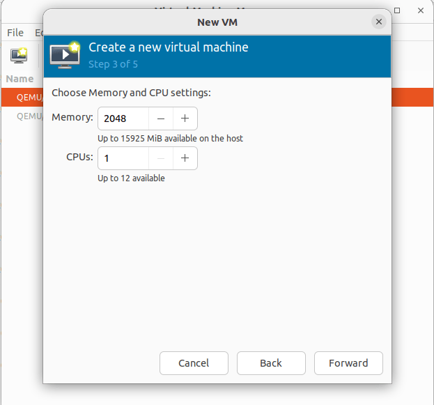
Set the desired memory and cpu settings for this vm
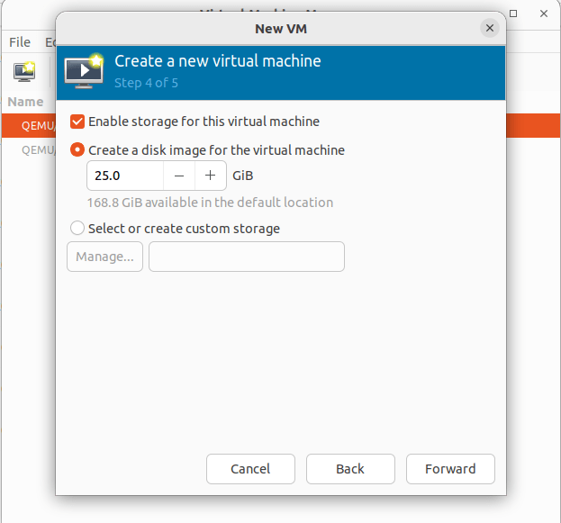
Create an hard drive image for the machine. You can change where the drive is located by clicking the Select or create customer storage option.
All storage options can be altered later. Just like the default for creating a vm.
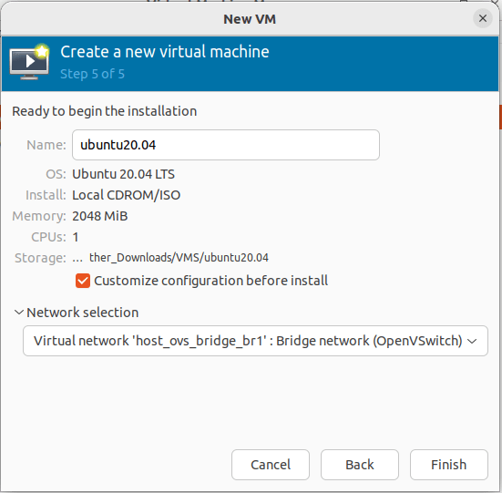
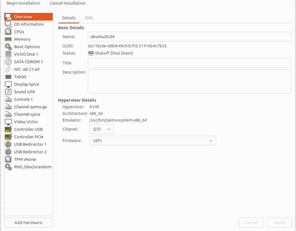
Changing the vm name can be done during or after creation. Click customer configuration before install to alter the vm before launching for install. This is needed if UEFI isn’t set as a default. The network selection should be set to our created openvswitch bridge.
Click finish, then select overview. If your OS requires UEFI to boot. Under the Hypervisor Details section, click the firmware tab and select UEFI. If everything is correct click begin installation.
Select you language of preference
If you have trouble viewing, click view>resize vm
At the above screen, we need to go back over to our command line.
Making a script will be much easier as the amount of vms grows.
We need to set the tagging so the vm can communicate.
Lets grab the last six of the mac address and add it to our script
You can get it from the installation screen as well
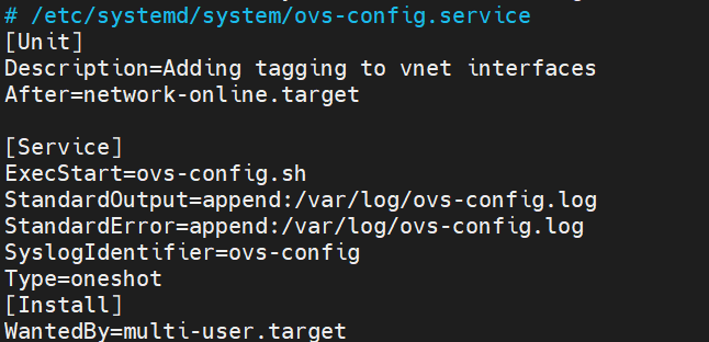
#You can place the script in one of the default system paths for programs.
sudo touch /usr/local/sbin/ovs-config.sh
sudo vi /usr/local/sbin/ovs-config.sh
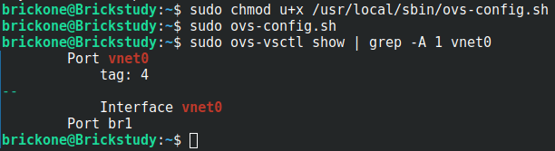
We need to make the script executable.
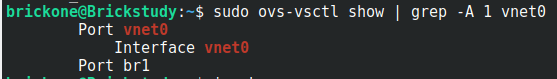
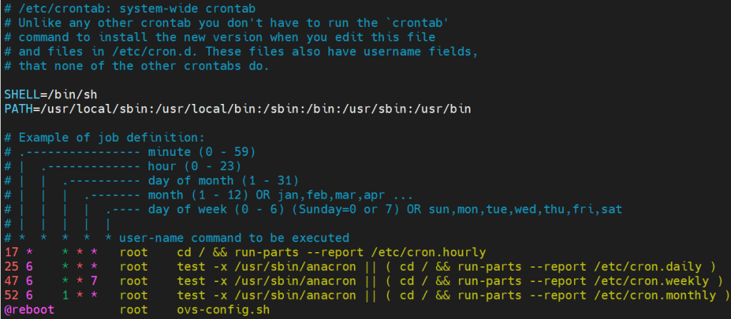
Then add it to a cron job. Whichever works best for you. When the VMs are restarted, the vnet interface is destroyed and is recreated when the VM comes back online.
We will make the script run on boot.
If this works correctly, our vm will be natively in vlan 4. It will also be able to communicate with vlan interfaces in any of the configured vlans on the trunk port.
Now our vm has network access
You will need to add tags to a vm’s interface whenever they are powered off and back on again.
I really enjoyed migrating from Hyper-V to kvm. I learned so much. Thank you for your time and have a great day!
If you need assistance finishing the installation. Here is the link to a Ubuntu installation tutorial.
In this post we will go over an initial configuration for a Juniper switch. I will be using a Juniper EX4200. The initial configuration is very similar for other Juniper devices. I will include links throughout the post for relevant information.
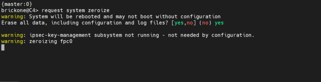
If you need to get back to factory default You can simply enter:
request system zeroize <– this will erase everything!
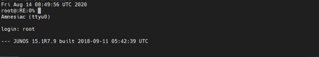
Below is how we will log in.
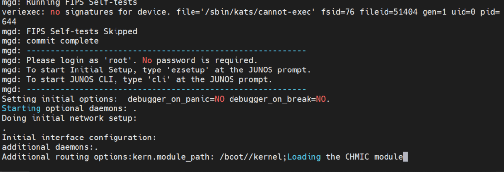
Factory default login prompt should show like below.
root@:RE:0% <– This is the freebsd shell. We leave this with the cli command
root@:RE:0% cli <– We leave this with cli
{master:0}
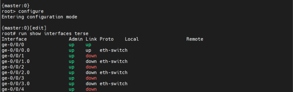
root> <– Operational mode prompt. Operational mode is used for monitoring and troubleshooting the device.
Operational mode is where we will do the most of our show commands. We can run operation commands from edit mode by placing the word run in front of the command.
There are two commands to enter edit mode. Both configure and edit will get you to edit mode.
Edit mode is where we will do majority of configuration. There are some configuration commands, mainly request or set date commands. That are executed in operational mode.
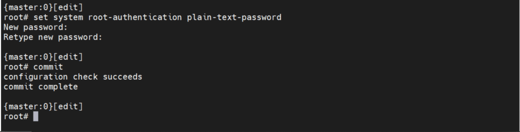
Before we can make any configuration changes, we need to set the system root-authentication.
The command is issued either at the top of the hierarchy [edit] or
[edit system root-authentication] hierarchy.
{master:0}[edit system root-authentication]
root# set plain-text-password <– Upon enter will prompt for password
Commit check <– Checks candidate configuration, does not apply it to active configuration
Commit confirmed # <– #= number in minutes between 1-65535. Default is 10m if no time is specified. Will apply candidate configuration to active configuration for time specified. Can be permanently configured by entering commit
Commit and-quit <– Commits candidate configuration to active and exits to operational mode.
The interesting thing about Juniper devices is the ability to rollback the configuration. By default Juniper keeps the last 50 (0-49) configurations. 0 being the active configuration. The configurations are sequentially moved after each commit.
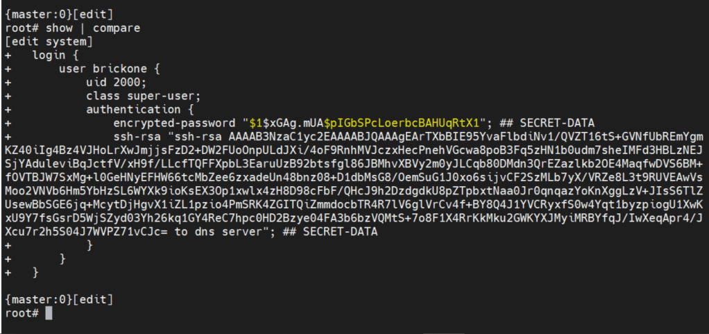
Now let’s create the user we will be using to login to our device.
set system login user brickone uid 2000 <– creates user and assigns specific user id
set system login user brickone class super-user <– You can assign a system defined user class, or create your own.
set system login user brickone authentication encrypted-password“$1$xGAg.mUA$pIGbSPcLoerbcBAHUqRtX1” <– You can paste in an encrypted password or use
set system login user brickone authentication plain-text-password
We can also set a private key if you have one
set system login user brickone authentication ssh-rsa “key here”
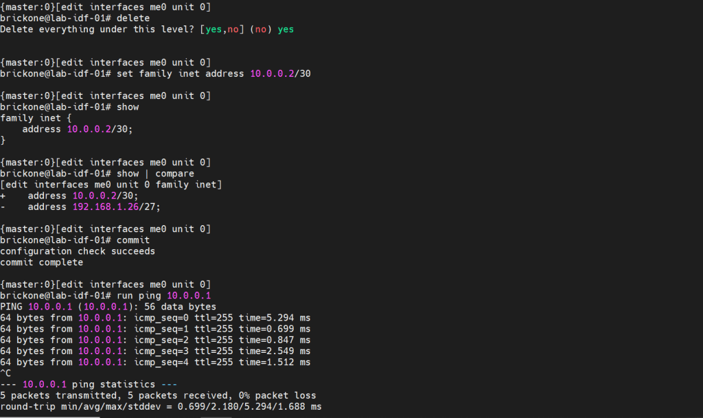
Whenever you are making changes or before a commit. You can use show | compare <– Shows differences of candidate configuration against active configuration.
Active configuration is the current configuration being utilized by the device
Candidate configuration is a copy of the active configuration in the device’s memory, created upon entering edit mode. No changes are implemented until a commit command is executed.
It’s important to set the device time and logging. Both are necessary for efficient troubleshooting. Depending on your setup, it could just be a single command.
set system ntp server 0.0.0.0 <– enter ntp server ip address
set date YYYYMMDDHHmm.ss <– Manually set system date & time
set system time-zoneAmerica/Detroit <– Change system time-zone
If your ntp server uses authentication (good idea) then the following commands may be closer to what you are looking for.
set system ntp boot-server 192.168.0.20 <–NTP server used upon boot
set system ntp authentication-key 1 type md5 <– NTP key & key algorithm
set system ntp authentication-key 1 value “$9$/x1ptpORESM8xGD” <– Juniper automatically encrypts passwords in configuration
set system ntp server 192.168.0.20 prefer <– Preferred NTP server
set system ntp trusted-key 1 <– Which key to use with server
With accurate system clock, comes accurate logging, which enables more efficient troubleshooting.
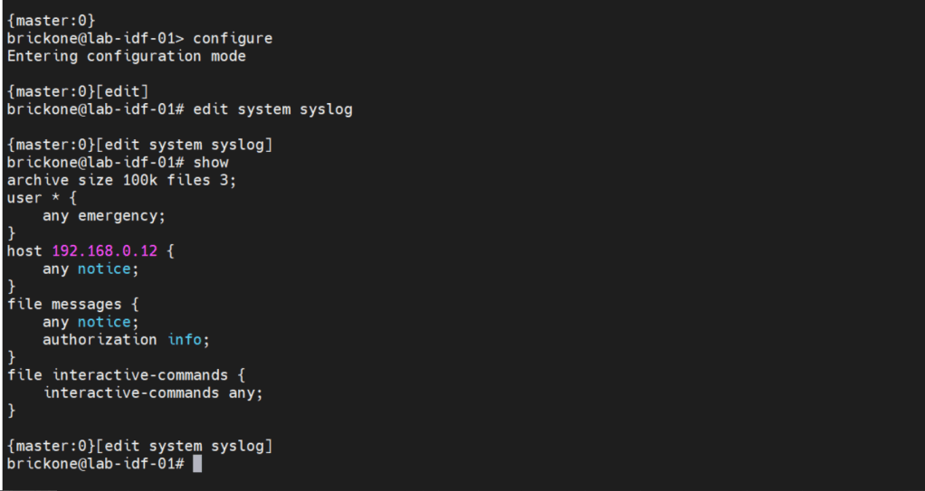
By default, log messages are sent to the messages log file.
To send log messages to a server we can navigate to the system syslog hierarchy. We can then set the server address, port, protocol, user to be notified of any or specific log events. We can alter a nice amount of log settings here, as well as change the file the device logs to.
That configuration will do us no good if we do not have any interfaces configured to pass traffic. A cool feature about juniper devices is that they come with a dedicated management interface. The management interface does not allow transit traffic. It is purely for managing the device. Configuring that interface is the same as our transit interfaces. Juniper devices require the configuration of a logical unit on the physical interface.
The family is the protocol that will be used to communicate on the logical interface. The interface must have a unit 0. The unit number is arbitrary, but mandatory.
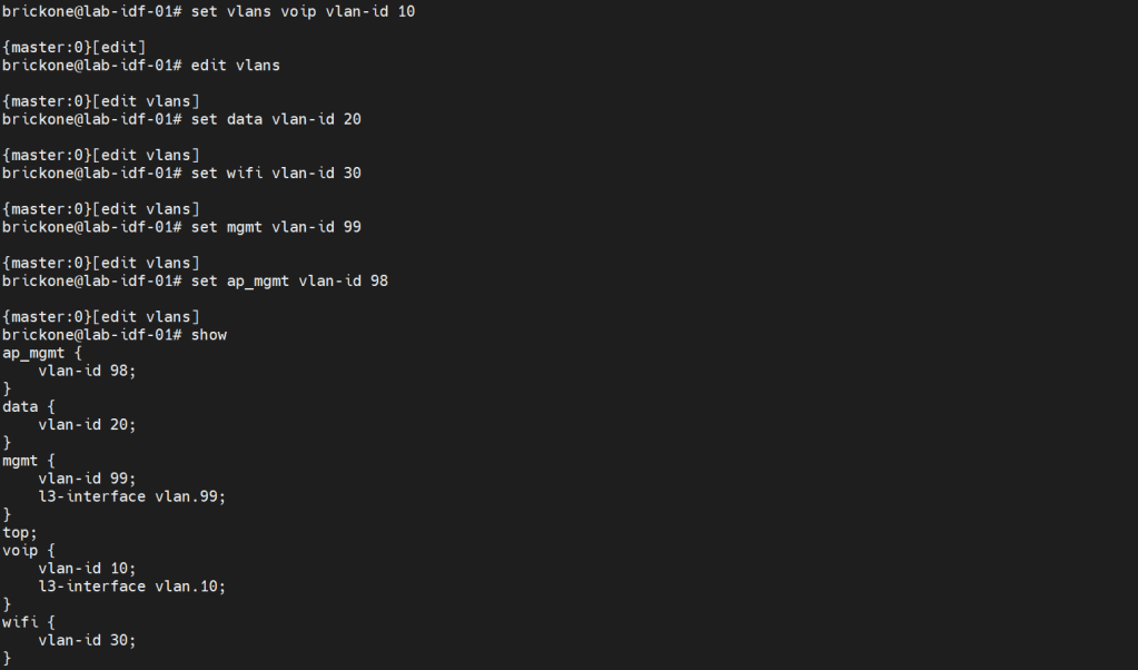
Configuring vlans is pretty straightforward. The vlan has to be specified by name, then assigned a tag value.
Set vlans name vlan-id #
root# set vlans MGMT vlan-id 99
To utilize our vlans, we need to configure our interfaces. We need access ports, which normally go to end devices. We also need to configure trunk ports which normally go to other networking devices. Good practice is to make interface ranges.
It is a very organized approach, but it’s important to remember that in the configuration. When there is a conflict, the range configured above the conflicting range will win.
Set interfaces interface-range name ? <– you configure this just like an interface.
Set interfaces interface-range name unit 0 family ethernet-switching
Set interfaces interface-range name unit 0 family inet
Set interfaces interface-range name description “description”
Set interfaces interface-range name member|member-range ge-0/0/# to ge-0/0/#
# You can set the vlan members either with name or number, the result is the same. You enable or disable poe on an interface with the set poe interface command. You can verify poe functionality with show poe controller operational mode command.
For trunk interfaces there are a few differences from other vendors that are worth noting. When a trunk interface is configured, you need to explicitly set the allowed vlans, and native vlan. The next part is that for our vlan interfaces. We need to create the vlan interface, then associate a vlan to it.
My ge-0/0/28 interface is connected to an upstream switch. It is good practice to limit the vlans allowed on a trunk port. Depending on your setup. The switch may do the routing for the vlan, or a router. All vlans don’t need a layer 3 interface configured. Remember that when configuring a Juniper device. As long as all the pieces are there during commit, the configuration will pass.
Set interfaces <interface> unit 0 family inet address <address/prefix>
Set vlans <vlan-name> vlan-id <#>
Set vlans <vlan-name> l3-interface <interface>
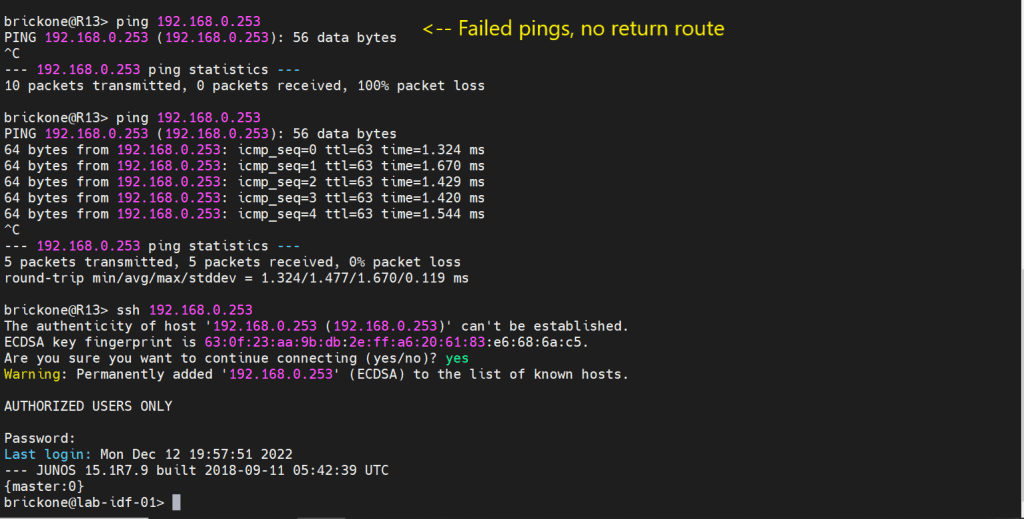
set interfaces vlan.99 family inet address 192.168.0.253/24
set vlans mgmt l3-interface vlan.99
set interfaces vlan.10 family inet address 10.0.10.2/24
set vlans voip l3-interface vlan.10
If we needed a DHCP server on our network. We could use our switch to facilitate this. I will configure it for one of our vlans.
#Configure DHCP service
Set system services dhcp-local-server <group-name> interface <interface>
Set system services dhcp-local-server group <group-name> interface <interface>
Set access address-assignment pool <pool-name> family <family> network <address/prefix>
#Range for DHCP pool
Set access address-assignment pool <pool-name> family <family> range <range-name> low <low-ip-address>
Set access address-assignment pool <pool-name> family <family> range <range-name> high <high-ip-address>
# Configure DHCP pool attributes
Set access address-assignment pool <pool-name> family <family> dhcp-attributes router <gateway-ip-address>
Set access address-assignment pool <pool-name> family <family> dhcp-attributes maximum-lease-time <seconds>
Set access address-assignment pool <pool-name> family <family> dhcp-attributes option <option-id-number> option-type <option-value>
# If you just paste a lot of set commands, it will overload the buffer. All the commands will not be accepted by the command prompt. Using the load set terminal will allow you to paste a large amount of set commands.
Configuring layer 2 security for our device will help mitigate some issues we may encounter down the line. There is always more we can do for security. We will keep it simple; we want to enable DHCP snooping for the vlans that will utilize DHCP. DHCP snooping builds a table, that maps the clients ip and mac address delivered by the DHCP server. It helps mitigate rogue DHCP servers, by designating a trusted port to allow DHCP server Offer messages.
We will add in DAI (Dynamic Arp Inspection); it uses that table as a list of authorized addresses that can perform arp requests. It protects against gratuitous arps, attempts to alter the flow of traffic for a host.
You can manually add mac addresses to the trusted list. You may also add manual DHCP snooping bindings to the tablet. It’s not very efficient, but it can help with troubleshooting.
IP source guard uses the DHCP snooping binding table. It uses this table to check if a host’s packets will be permitted or denied. If the packet on an untrusted port is not matched in the DHCP snooping table. It is discarded. By default, on Juniper trunk interfaces are trusted for DHCP snooping, IP source guard, and DAI.
Mac limiting on an interface, is a way to protect from mac flooding attacks. They are used to overload the cam table. Once no more mac address can be learned. All traffic is flooded, essentially turning our switch into a hub.
All four are configured under the Ethernet-switching-options secure-access-port hierarchy
#Configure DHCP snooping
set vlan <vlan-name> examine-dhcp
set vlan <all> examine-dhcp
#Configure DHCP Snooping Manual Binding
set ethernet-switching-options secure-access-port interface <interface> static-ip <ip-address> vlan <vlan-name> mac <mac-address>
set interface <interface> static-ip <ip-addr> vlan <#> mac <mac-addr>
#Configure DAI
set vlan <vlan-name> arp-inspection
set vlan<all> arp-inspection
#Configure Static Arp table entry
[edit interfaces <interface> unit <#> family <family> address <address>]
set arp ip-address mac <mac-address>
#Configure IP source guard
set vlan <vlan-name> ip-source-guard
set vlan<all> ip-source-guard
#Configure Mac limiting
set interface <interface> mac-limit # action <action>
set interface <all> mac-limit # action <action>
[edit vlans]
set <vlan> mac-limit # action <action>
#Configure Static Mac
set interface <interface> allowed-mac <mac-address>
#If you need to isolate device communication in a vlan
[edit vlans]
set <vlan> no-local-switching
The action drop will just drop packets of the exceeding mac address on the port. You could also have the port disable, then re-enable after a certain amount of time, just like with BPDU errors.
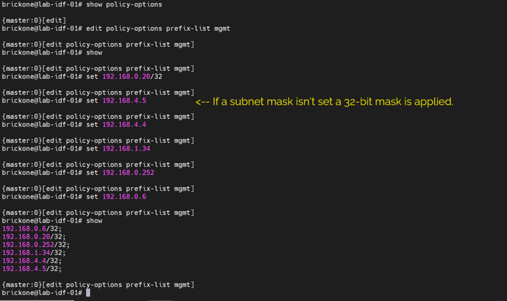
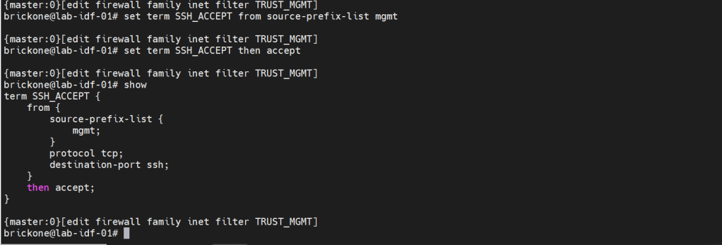
We will secure our device further by only allowing specific subnets or hosts to remotely access our device. On Juniper devices we will use a firewall filter to discriminate control plane traffic destined for the routing engine. We want to make sure we do not lock ourselves out of the device. As well as drop other traffic. At the end of all firewall filters, there is an implicit deny any. Juniper firewall filters use terms with from for matching, then for action statements. The steps are simple, we will configure our prefix list, apply it in a firewall filter configuration, along with our other match conditions. We will add an accept all at the end of the firewall filter. Then apply the firewall filter to our loopback interface.
#Create prefix-list
set policy-options prefix-list <name> <ip-address/prefix>
set firewall family <family> filter <name> term <term-name> from <match condition>
set firewall family <family> filter <name> term <term-name> then <action>
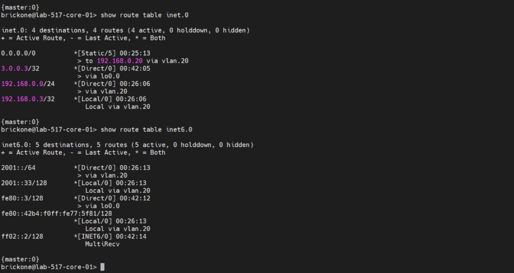
Before we configure our firewall filter, we need to configure connectivity. The only devices our switch can reach are directly connected devices. Since those will be the only routes in the routing table without administrative intervention. Because this device only has one path off the network. We will just configure a default route to our next-hop device.
#Static route configuration
set routing-options static route 0.0.0.0/0 next-hop <ip-address>
set routing-options static route 0/0 next-hop 192.168.0.20
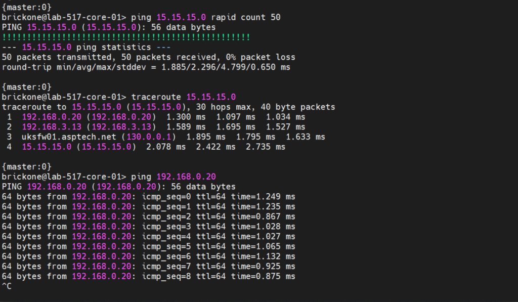
To verify that our switch is operating as we expected. We need to run show commands to verify reach-ability.
That’s all for now. Be wary when buying used gear, for labs it’s fine. My 48 port and 24 port ex4200’s dhcp snooping did not function at all. As always thank you for your time, and have a great day.
One of the coolest moments in troubleshooting is when the device tells you what is happening.
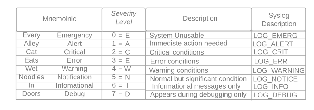
Syslog messages let us know events transpiring on our Cisco devices. We can store logs in the device ram, an external server, or on non-volatile storage on the device.
Defaults:
By default all logging is sent to the console port
Default logging level debugging (7) for console, monitor, and buffer.
Trap logging defaults to informational (6)
Buffer logging default size 8192, once filled older messages are deleted.
Service timestamps log|debug datetime – is the default for log messages. Log messages time will match UTC time.
Logging rate-limit default is 10 log messages per second.
If nothing different is specified UDP port 514 is used for host logging.
Console logging – all messages are sent to the console port.
Monitor logging- messages are displayed on the VTY lines of the device.
Buffered logging – stores the log messages using a circular buffer in the devices ram.
Exception logging – The main purpose of it is to restrict or disable the amount of buffered log sent to the console on a system crash
Persistent logging – stores the log messages from ram buffer to devices flash disk
Embedded Syslog Manager (ESM) uses syslog filter modules to process system logging messages. Syslog filter modules are scripts written in the Tool Command Language (Tcl) stored in local system memory or on a remote file server.
Host logging (syslog) – forwards log messages to an external syslog server.
SNMP logging – uses SNMP traps to send log messages to an external SNMP server.
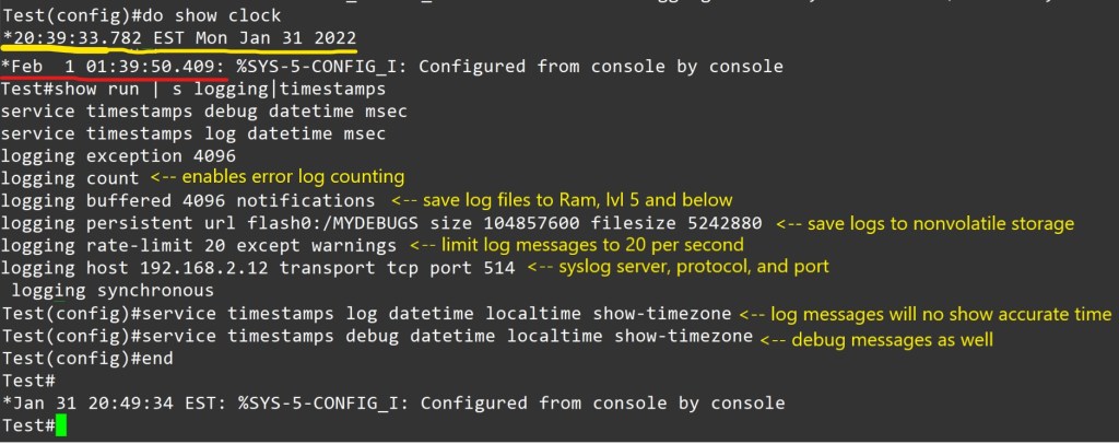
For proper logging, it is best practice to configure the device’s clock. It is recommended to use ntp.
Configuration to allow logging to all three, ram, server, and flash.
Notes – Using buffered or persistent logging takes away system resources. I should be used cautiously. Verify connectivity to server, port and protocol. Verify service timestamps and ntp settings when facing logging time inconsistencies.
Conditional Debug:
Making a debug as tuned as possible is awesome. Here is an example.
Conditions are turned on with the command
Router# debug condition < parameter>
Ex- Router# debug condition ip 192.168.0.1
Router# debug condition interface g0/1
Router# show debug <– view debugs and conditions
Debugs are removed with no debug condition <#>
Ex- Router# no debug condition 1
When removing the last debug condition you will be prompted.
Debugs without conditions.
I would experiment with this in a lab on the same IOS version you plan to use in a different environment. Turning on debugs is taking the packets from the data plane and sending it to the control plane. You can brick a device or cause it to restart. Not good for professional environments.
As always thank you for your time.
-Notes
By default, the console port processes all debug output, even when it is logging messages to an internal buffer or when it is sending the debug output to a vty or aux port. A router will prioritize console output; therfore sending a significant amount of debug output to the console port can cause the router to hang. To prevent this from occurring, you should issue the no logging console command unless you are actively logging to the console port. In addition, if you must capture large amounts of debug output, you should always send the output to a vty port. to the aux port, or to an internal logging buffer.
The no logging on command will cause debug messages to appear only on the console, thereby disabling logging to the vty port, aux port and internal buffers.
We will be installing Nagios to monitor our Cisco devices via SNMP . The device config is brief compared to the server config. I will accompany config with screenshots, as well as links at the bottom. I will be using a Ubuntu 20.04 , Cisco 3560 15.2(2) , and Cisco 194115.0(1) .
Pre-requisites:
A Cisco device (physical or virtual) to configure and poll
Not so much a must, but having a nice amount of free time to do projects helps. Troubleshooting can pop up, or you could just want to delve further into the subject. I also suggest note taking, whichever form.
Cisco Device Configuration:
-V2c
Router(config)# ip access-list standard <ACL-Name>
Router(config-std-acl)#permit <server ip address>
Router(config)# snmp-server community <chosen community string> RO <ACL-Name>
Router(config)# snmp-server location <location>
Router(config)# snmp-server contact <contact>
Router(config)# ip domain-name <domain-name>
Router(config)# snmp-server ifindex persist <– Router keeps same interface index even after reboot.
-v3
Router(config)#snmp-server view VIEW1 internet included <– Creates VIEW1 with access to everything
Router(config)#snmp-server group GROUP1 v3 priv read VIEW1 write VIEW1<– Create v3 group assigned view VIEW1 Router(config)#snmp-server user bob GROUP1 v3 auth sha cisco123 priv aes 128 juniper1 <– Creates user bob nested in GROUP1, authentication hashing algorithm is sha. Authentication password is cisco123. Encryption algorithm is aes 128 with password juniper1
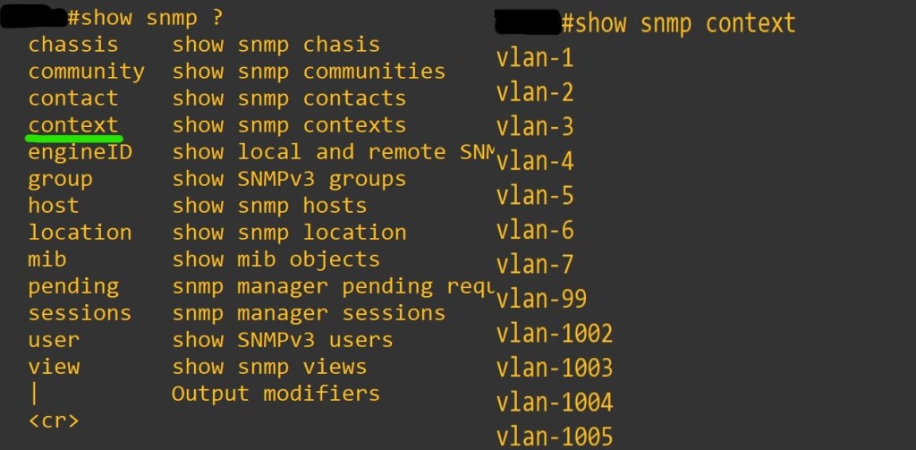
Router(config)#snmp-server group GROUP1 v3 auth context vlan- match prefix <– You must use contexts to get per-VLAN data from the BRIDGE-MIB with SNMPv3.Not all the IOS switches support this. In general, if the device supports the “show snmp context” command, contexts will work. If not, an upgrade is needed. However, some switches (e.g. 2950 series) will never support SNMPv3 contexts. You must use v1/v2c with these switches.
Router(config)# snmp-server ifindex persist <– Router keeps same interface index even after reboot.
Device needs context configuration if this command is present.
The error I experienced with no context configured.
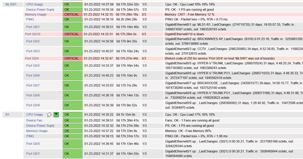
The result we want from snmpwalk command. Ctrl+c to end the massive stream of text.
Now the Nagios Server. I thought text would be more appropriate for copy and paste. I know we all get enough typing practice.
sudo apt update -Install Dependencies sudo apt install -y autoconf bc gawk dc build-essential gcc libc6 make wget unzip apache2 php libapache2-mod-php libgd-dev libmcrypt-dev make libssl-dev snmp libnet-snmp-perl gettext -Navigate to home directory cd ~/ -Download Nagios Core 4.4.6 sudo wget https://github.com/NagiosEnterprises/nagioscore/archive/nagios-4.4.6.tar.gz -Extract the Nagios Package and navigate to extracted Nagios Directory sudo tar -xf nagios-4.4.6.tar.gz cd nagioscore-*/ -Compile and Install Nagios sudo ./configure –with-httpd-conf=/etc/apache2/sites-enabled sudo make all -Create the Nadios user and group, and add the ‘www-data’ Apache user to the ‘nagios’ group sudo make install-groups-users sudo make install-commandmodeudo usermod -a -G nagios www-data -Install Nagios binaries, service daemon script, and the command mode. sudo make install sudo make install-daemoninit sudo make install-commandmode -Install the sample script configuration sudo make install-config -Install the Apache configuration for Nadios and activate the mod_rewrite and mode_cgi modules. sudo make install-webconf sudo a2enmod rewrite cgi -Restart Apache service sudo systemctl restart apache2
-Create nagiosadmin user. This is the user we will use to login to web interface. sudo htpasswd -c /usr/local/nagios/etc/htpasswd.users nagiosadmin
-Setup UFW Firewall sudo ufw allow apache sudo ufw allow ssh sudo ufw enable y sudo ufw status numbered -Install Nagios Plugins and NRPE Plugin sudo apt install monitoring-plugins nagios-nrpe-plugin -Once installation completes go to the nagios installation directory /usr/local/nagios/etc cd /usr/local/nagios/etc sudo mkdir -p cisco/{remotehosts,commands,servicegroups,hostgroups} -Now we need to edit Nagios config to load our config directory sudo vi nagios.cfg -add line cfg_dir=/usr/local/nagios/etc/cisco :wq save and close
sudo apt install tree
-The two plugins downloaded at the beginning must be placed into the /usr/local/nagios/libexec dir
-Let’s create a hostgroup for out cisco devices
cd /usr/local/nagios/cisco
sudo vi hostgroups/cisco-devices.cfg
– add this text
define hostgroup{ hostgroup_name cisco-devices alias Cisco_devices }
-save and close
-Then we need to define our hosts and services
sudo vi remotehosts/<hostname>.cfg
define service{ use generic-service host_name <hostname> service_description CPU Usage check_command check_cisco_switch!<community-string>!cpu!60!70 servicegroups cpu-usage }
define service{ use generic-service host_name <hostname> service_description Device Fan check_command check_cisco_switch!<community-string>!fan servicegroups device-fan } define service{ use generic-service host_name <hostname> service_description Device Power Suply check_command check_cisco_switch!<community-string>!ps servicegroups device-powersupply }
define service{ use generic-service host_name <hostname> service_description Port G0/0 check_command check_cisco_int!<community-string>!G0/0 servicegroups cisco-interfacestatus }
define service{ use generic-service host_name <hostname> service_description Port G0/1 check_command check_cisco_int!<community-string>!G0/1 servicegroups cisco-interfacestatus }
-You can add and remove services as you like, just remember the commands. Example is my 3560 doesn’t have a fans, so I removed that service.
-Next service groups
sudo vi servicegroups/cisco-services.cfg
define servicegroup{ servicegroup_name memory-usage alias Memory Usage }
define servicegroup{ servicegroup_name cpu-usage alias CPU Usage }
define servicegroup{ servicegroup_name device-fan alias Device Fan }
define servicegroup{ servicegroup_name device-powersupply alias Device Power Supply }
define servicegroup{ servicegroup_name cisco-interfacestatus alias Cisco Interface Status }
As always thank you for your time. There is so much more to learn about device management. Nagios isn’t perfect but projects like this deal with quite a bit of troubleshooting. I find them great to learn about things you would of otherwise just skimmed by.